


Appendix B ~ Pinouts
20
Technical Services Group ~ 1-800-283-5936 (USA) ~ 1-801-974-3760
All commands are
momentary.
Appendix B: Pinouts
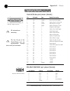
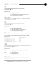
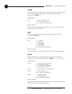
RS-232 COM DCE port pinout (female)
Pin Number Control Pin Number Control
1 DCD 6 DSR
2 TXD 7 CTS
3 RXD 8 RTS
4 DTR 9 No connection
5 Ground
1
5
6
9
Figure B.2. RS-232 connector
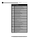
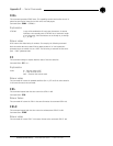
Control/Status port pinout (female)
Pin Definable Type Default Description
1 Yes Control Aux In to Aux Out toggle
2 Yes Status Status of Aux In to Aux Out
3 Yes Control Mute Mic/Line In toggle
4 Yes Status Status of Mic/Line In mute
5 Yes C Telephone On/Off toggle
6 Yes S Status of tel. On/Off toggle
7 Yes C Auto Answer toggle
8 Yes S Status of Auto Answer
9 Yes C Mute Line Out toggle
10 Yes S Status of Line Out mute
11 Yes C Mute 4-Wire In toggle
12 Yes S Status of 4-Wire In mute
13 Yes C Volume up Speaker/Line (1dB)
14 Yes S No connection
15 Yes C Volume down Spkr/Line (1dB)
16 Yes S No connection
17 No S No connection
18 No S No connection
19 No S No connection
20 No S No connection
21 No S Ring indication
22 No S No connection
23 No S +5VDC
24 No S +5VDC
25 No Ground Ground
13
25
1
14
Figure B.1. DB-25 connector
✍
The first 16 pins of the
Control/Status port are
programmable through
direct serial port commands.
✍