FLOW RATE MEASUREMENTS
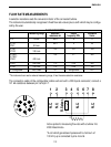
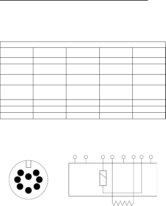
A selection resistance sets the conversion factor of the connected turbine.
The instrument automatically recognises 5 fixed flow rate values plus a sixth which may be configu-
red by the user.
*The instrument can read a reduced measuring range, it has the same selection resistance.
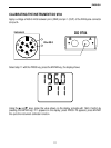
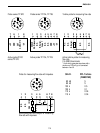
The connection cable of the configurable turbine will end with a DIN 8-pole connector; connect a
121 kΩ resistance between pin 3 and pin 7.
Active probe for measuring flow rate with a turbine 2 to
2000 litres/minute.
*A coil which generates impulses with a minimum of
100 mV p-p is connected to pins 4 and 6.
ENGLISH
112
FLOW RATE PROBES
Measuring range Selection Output Indication
resistance kΩ frequency PPL lt/min.
LT 5 5 l/min. 90.9 5 5
(LT10)* 95.3 5 20
LT20 20 l/min.
(LT50)* 100 0.5 125
LT125 125 l/min.
(LT250)* 105 0.1 400
(LT300)*
LT400 400 l/min.
LT500 500 l/min. 110 0.04 500
LT750 750 l/min. 115 0.04 750
LT configurable 2000 l/max 121 configurable PPL
6
1
4
7
3
5
8
2
N.C.
1
N.C.
5 73 4 6
N.C.
R. Select.
2
N.C.
8
*


