


Quick Installation Guide
00825-0100-4716, Rev DA
October 2009
Rosemount 3095 MultiVariable
14
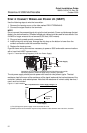
STEP 5: CONFIGURE THE TRANSMITTER (HART)
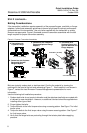
Setting the Loop to Manual
Set the process application loop to manual when preparing to send or request data that
would disrupt the loop or change the output of the transmitter. A prompt will appear
reminding the user to set the loop to manual when necessary. Acknowledging this prompter
does not set the loop to manual.
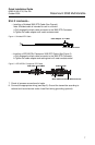
Send the Configuration to the Transmitter
Use the following steps to send the configuration to the transmitter. All previous transmitter
information will be overwritten when the information is sent.
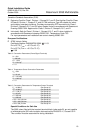
1. EA: Select C
onfigure > Configure Flow.
2. Step through the Flow Configuration wizard.
3. Check Sen
d Flow Configuration to update the transmitter’s flow calculation.
4. From the Device Connection window, right click on the transmitter icon, and select
Configuration Properties. On the Basic Setup window, verify the units of measure and
the LRV to URV range (4-20 mA setpoints).
Basic Configuration Parameters
NOTE:
A check (✓) indicates the basic configuration parameters. At minimum, these parameters
should be verified as part of the configuration and startup procedure.
Transmitters are shipped from Emerson Process Management fully calibrated and
configured for the application when C2 Option is ordered. Without C2 Option, configuration
will be by the factory default.
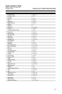
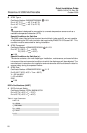
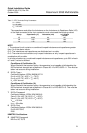
Table 2. HART Communicator Fast Key Sequence
Function/Variable Fast Key Sequence
% rnge 1, 1, 2
% rnge 1, 1, 5, 1, 3
4V is 1, 1, 5, 4, 1
AO Alrm typ 1, 4, 1, 1, 1
AO1 1, 1, 3
AO1 3
AP Damping 1, 4, 2, 5, 2
AP Sens Trim 1, 2, 2, 1, 2
AP Units 1, 3, 2, 2
Absolute (AP) 1, 1, 4, 2
Atm Press Cnfg 1, 4, 2, 3
Burst mode 1, 4, 1, 2, 4, 2
Burst option 1, 4, 1, 2, 4, 1
Change PV Assgn 1, 1, 5, 1, 5
Change SV Assgn 1, 1, 5, 2, 3
Change TV Assgn 1, 1, 5, 3, 3
Change 4V Assgn 1, 1, 5, 4, 3
D/A trim 1, 2, 2, 2, 1
DP Low Flow Cutoff 1, 4, 6
DP LRV 4