


Quick Installation Guide
00825-0100-4716, Rev DA
October 2009
Rosemount 3095 MultiVariable
21
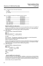
The capacitance and either the Inductance or the Inductance to Resistance Ratio (L/R)
of the load connected to the 4-pin connector must not exceed the following values:
NOTE
1. The external circuit contains no combined lumped inductance and capacitance greater
than 1% of the above values.
Or 2. The inductance and capacitance are distributed as in a cable.
Or 3. The external circuit contains only lumped inductance or only lumped capacitance in
combination with a cable.
In all other situations e.g. combined lumped inductance and capacitance, up to 50% of each
of L and C values is allowed.
Conditions of Certification (X):
When fitted with the transient option, the apparatus is not capable of withstanding the
500V electrical strength test as defined in Clause 6.3.12 of IEC 60079-11. This must be
taken into account during installation.
5 IECEx Type n
Certificate Number: IECEx BAS06.0071X
Ex nA nL IIC T4 (-45°C T
a
70°C)
Ex nA nL IIC T5 (-45°C T
a
40°C)
U
i
= 55V dc max
Conditions of Certification (X):
When fitted with the transient option, the apparatus is not capable of withstanding the
500V electrical strength test as defined in Clause 6.8.1 of IEC 60079-15. This must be
taken into account during installation.
7 IECEx Flameproof
Certificate Number: IECEx KEM 06.0018
Zone 0/1 Ex d IIC T6 (-20°C T
a
65°C)
Zone 0/1 Ex d IIC T5 (-20°C T
a
80°C)
V
max
= 55 Vdc
I
max
= 23 mAdc
8 IECEx Dust
Certificate Number: IECEx KEM 06.0018
Ex tD A22 T90°C
IP66
INMETRO Certifications
E INMETRO Flameproof
BR-Ex d IIC T6/T5
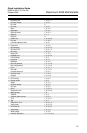
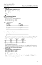
Table 7. RTD Terminals Entity Parameters
U
o
= 30Vdc
I
o
= 19 mAdc
P
o
= 140 mW
Group Capacitance (F) Inductance (mH) or L/R Ratio
H/Ohm
IIC 0.066 96 247
IIB 0.56 365 633
IIA 1.82 696 633