


Quick Installation Guide
00825-0100-4716, Rev DA
October 2009
Rosemount 3095 MultiVariable
6
STEP 2 CONTINUED...
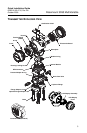
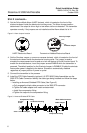
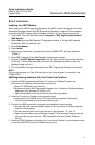
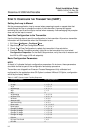
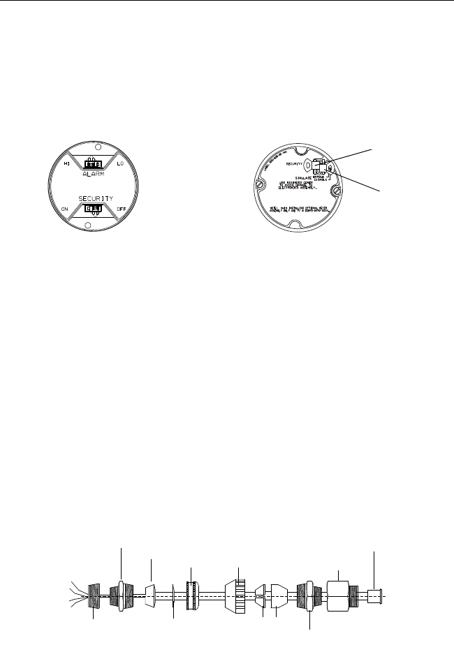
3. Set the Failure Mode Alarm (HART devices), which is located on the front of the
electronics board inside the electronics housing cover. The Alarm Jumper position
determines if the output is driven high or low when a failure is detected. The transmitter
operates normally if the jumpers are not installed and the Alarm default fail is HI.
Figure 2. Alarm Jumper Location
4. Set the Simulate Jumper (FOUNDATION fieldbus devices), which is located on the front of
the electronics board inside the electronics housing cover. The jumper is used to
simulate the measurement and is used as a lock-out feature for the AI function block. To
enable the simulate feature, insert the jumper across ENABLE while the transmitter is
powered. The default position for the Simulate Jumper is DISABLE. Enable the simulate
feature after power is applied to the device. Simulate is automatically disabled
regardless of jumper position if power is cycled.
5. Connect the transmitter to the process.
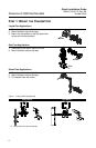
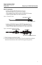
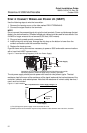
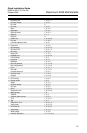
6. Install the RTD Cable Assembly (optional). All RTD 3095 Cable Assemblies use the
3095 RTD Cable Connector. Identify the cable type being installed and follow the steps
below.
• Installing an Armored Shielded RTD Cable (See Figure 3)
a.Fully engage the black cable connector to the 3095 RTD connector.
b.Tighten the cable adapter until metal contacts metal.
c.Install the compression fitting.
d.Tighten the cap onto the compression fitting.
Figure 3. Armored Shielded RTD Cable
HART Electronics Board
F
OUNDATION fieldbus Electronics Board
Simulate Jumper
Security Jumper
Washer
Cap
Black Cable Connector
RTD Cap
Conductive Bushing
Connect
to RTD
Compression Fitting
Compression Fitting
Cable Adapter
3
/4 to
1
/2-14 NPTAdapter
Bushing