


U.S. ELECTRICAL MOTORS
INSTALLATION AND MAINTENANCE
VI. INITIAL INSTALLATION
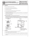
1. Coupling or Pulley Installation
Remove the shaft locking device shipped on motor (as applicable). Wash protective coating from the motor
shaft extension(s) with solvent. Install couplings or pulleys on motor shaft per manufacturers' recommended
fit and mounting practices.
Caution: Hammering or pounding with a mallet to install couplings or pulleys will
damage bearings.
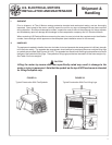
In belted applications, the driver pulley should be positioned as close to the shaft shoulder as possible to
assure longest bearing life and keep shaft bending moment to a minimum. Take care to ensure that the
inboard edge of the pulley hub does not ride-up on the shaft shoulder blend radius.
Caution: Belt tension should not exceed the transmission drive manufacturers'
recommendations. Excessive belt tension reduces belt life. Overload due
to overtensioning of belts reduces bearing life and can induce shaft fatigue
failure.
Caution: Excessive bending movement due to placing of pulley far out on the shaft
extension will reduce bearing life and may lead to shaft fatigue failure.
Caution: Placing the pulley hub onto shaft against the shaft shoulder blend radius
may cause a large stress riser in the shaft, resulting in shaft fatigue failure.
Prevent this from occurring by using a chamfered spacer ring or chamfering
the end of the hub bore.
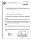
2. Rough Alignment
Inspect sole plate mounting pads and bottom of motor feet for dirt or irregularities that would prevent proper
seating. Position and shim the motor such that the coupling hubs are aligned within 1/32" and the motor shaft
is level. The motor shaft must be slightly lower than the driven shaft to allow for final adjustment shims.
3. Final Alignment
Accurate shaft alignment between motor and driven equipment is essential for trouble-free operation. Im-
proper alignment can result in vibration, bearing overload and excessive shaft stresses. Flexible couplings
may not adequately compensate for excessive misalignment.
Whenever aligning a motor to driven equipment, keep the following rules in mind:
– Do not place more than five shims in a shim pack under any one machine foot, as the flexibility of the shim
pack will contribute to a soft foot condition.
– After any corrective adjustment, tighten foot bolts securely and recheck alignment.
– When making shim adjustments, change only one foot at a time.
– Recheck alignment after the motor has been in service for approximately one week and readjust as
necessary.
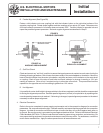
A. Angular Alignment (See Figure 3A)
Check for angular misalignment of motor to driven unit shaft. (See Figure 3A). Measure distance between
coupling hub faces (with feeler gauges) at four places equally spaced around the outside diameters. Position
motor as necessary to be within the maximum allowable misalignment of .001 in. per foot of coupling radius.
Initial
Installation
6