


U.S. ELECTRICAL MOTORS
INSTALLATION AND MAINTENANCE
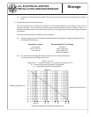
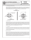
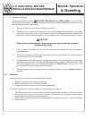
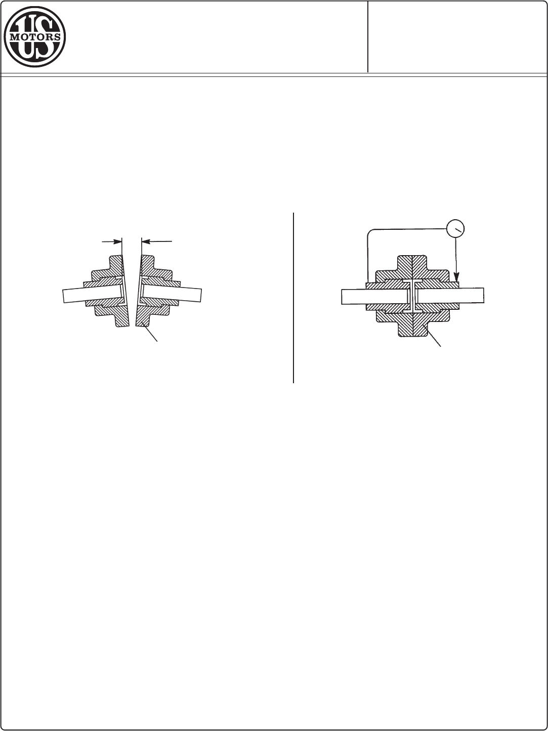
B. Parallel Alignment (See Figure 3B)
Fasten a dial indicator onto one coupling hub with the indicator button on the cylindrical surface of the
opposite coupling hub. Rotate shafts together and take readings at four points, 90° apart. Relocate motor
until total indicator movement in full rotation does not exceed .002". Transfer indicator to opposite hub and
repeat the parallel alignment procedure. Recheck angular alignment as described in Step A.
FIGURE 3
FLEXIBLE COUPLINGS
C. Soft Foot Check
Check and correct any "soft foot" condition to assure that equal pressure is exerted on each motor foot by the
following shimming procedure. Bolt all motor feet down solidly to the motor bedplate or foundation. Mount the
base of the dial indicator from the motor's foundation, and place and zero out the indicator on the motor shaft
or coupling. Back off one of the take off end bolts and check indicator for change in reading, a .001 inch
reading is maximum. Shim at foot if required and go to other take off end bolt. This procedure should be
repeated on the opposite end until no reading is greater than .001 inches.
D. Hot Alignment
It is possible for motor shaft height to change relative to the driven equipment and this should be compensated
for during the alignment procedure. Recheck parallel alignment (vertical) of coupled drive by repeating after
normal operating temperature is reached. If shimming is changed, repeat alignment procedure to the extent
necessary to assure proper alignment.
4. Electrical Connection
Refer to the motor nameplate for power supply requirements and to the connection diagram for connection
parameters. Be sure connections are tight. Recheck carefully and assure that they agree with the connection
diagram. Insulate all connections with electrical tape to insure that they will not short against each other or
to ground. Be sure the motor is grounded to guard against electrical shock. Refer to the National Electrical
Code Handbook (NFPA No. 70) and to local electrical codes for proper wiring, protection, and wire sizing. Be
sure proper starting equipment and protective devices are used for every motor. For assistance, contact the
motor starter manufacturer. Apply the above precautions to all accessories as well.
Initial
Installation
7
FLANGE
MOTOR
LOAD
FIGURE 3A
ANGULAR MISALIGNMENT
FIGURE 3B
PARALLEL ALIGNMENT
FLANGE
LOAD
MEASURE DISTANCE
BETWEEN FACES
MOTOR