


May 2014
12
Quick Start Guide
Step 5: Wire and apply power
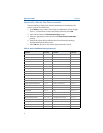
Wire the transmitter
Wiring diagrams are located inside the terminal block cover.
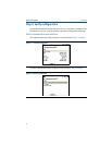
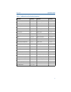
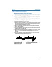
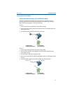
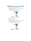
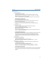
Figure 4. Sensor Connections Diagram
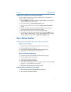
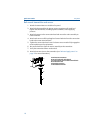
Power the transmitter
1. An external power supply is required to operate the transmitter.
2. Remove the terminal block cover (if applicable).
3. Connect the positive power lead to the “+” terminal. Connect
the negative power lead to the “–” terminal.
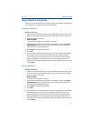
4. Tighten the terminal screws. When tightening the sensor and power wires, the
max torque is 6 in.-lbs (0.7 N-m).
5. Reattach and tighten the cover (if applicable).
6. Apply power (12 – 42 Vdc).
Load limitation
The power required across the transmitter power terminals is 12 to 42.4 Vdc
(the power terminals are rated to 42.4 Vdc). To prevent damaging the
transmitter, do not allow terminal voltage to drop below 12.0 Vdc when
changing the configuration parameters.
(1) The transmitters must be configured for at least a 3-wire RTD in order to recognize an RTD with a compensation loop.
(2) Rosemount Inc. provides 4-wire sensors for all single element RTDs. Use these RTDs in 3-wire configurations by
leaving the unneeded leads disconnected and insulated with electrical tape.
644H 644R
A. Sensor terminals
B. Communication terminals
C. Power/Configuration terminals
2-wire
RTD and ⍀
3-wire
RTD
and ⍀
(2)
4-wire
RTD
and ⍀
T/C
and mV
(1)
1234
1234
1234
1234
1 2 3 4
A
B
C
A
C
Max torque is
6 in.-lbs (0/7 N-m)