


May 2014
6
Quick Start Guide
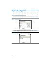
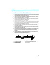
Input/verify Callendar Van-Dusen constants
If sensor matching is being used with this combination of a transmitter and
sensor, verify the constants input.
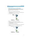
1. At the Home screen, select 1 Device Setup, 3 Configuration, 2 Sensor Config, 1
Sensor 1, 3 Cal Van-Dusen. Set the control loop to manual. Select OK.
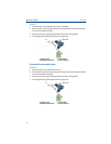
2. Select Cal Van-Dusen at the Enter Sensor Type prompt.
3. Select the appropriate number of wires at the Enter Sensor Connection
prompt.
4. Enter the R
o
, Alpha, Beta, and Delta values from the stainless steel tag
attached to the special-order sensor.
5. Select OK after you return the control loop to automatic control.
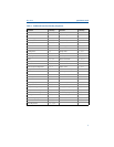
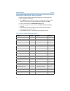
Table 2. Device Dashboard Fast Key Sequences
Function Fast Keys Function Fast Keys
Active Calibrator 2, 2, 4, 2 Num Req Preams 2, 2, 5, 2
Alarm/Saturation 2, 2, 2, 6 Open Sensor Holdoff 2, 2, 4, 4
Burst Mode 2, 2, 5, 3 Percent Range 2, 2, 2, 4
Burst Option 2, 2, 5, 4 Poll Address 2, 2, 5, 1
Calibration 2, 1, 2 PV Damping 2, 2, 1, 6
Callendar-Van Dusen 2, 2, 1, 10 PV Unit 2, 2, 1, 4
Configuration 2, 1, 1 Range Values 2, 2, 2, 5
D/A Trim 3, 4, 2 Scaled D/A Trim 3, 4, 3
Damping Values 2, 2, 1, 6 Sensor Connection 2, 2, 1, 3
Date 1, 7, 8 Sensor 1 Setup 2, 2, 1
Descriptor 1, 7, 6 Sensor Serial Number 2, 2, 1, 7
Device Info 1, 7 Sensor 1 Trim 3, 4, 1
Device Output Configuration 2, 2, 2 Sensor 1 Trim-Factory 3, 4, 1, 2
Filter 50/60 Hz 2, 2, 4, 7, 1 Sensor Type 2, 2, 1, 2
Hardware Rev 1, 7, 9, 3 Software Revision 1, 7, 9, 4
Hart Output 2, 2, 5 Ta g 2, 2, 4, 1, 1
LCD Display Options 2, 2, 3 Terminal Temperature 3, 3, 2
Loop Test 3, 5, 1 URV (Upper Range Value) 2, 2, 2, 5, 2
LRV (Lower Range Value) 2, 2, 2, 5, 3 USL (Upper Sensor Limit) 2, 2, 1, 8
LSL (Lower Sensor Limit) 2, 2, 1, 9 Variable Mapping 2, 2, 5, 5
Message 1, 7, 7 Variable Re-Map 2, 2, 5, 5, 5
Meter Configuring 2, 2, 3, 1 Write Protect 2, 2, 4, 6
Meter Decimal Point 2, 2, 3, 2 2-Wire Offset 2, 2, 1, 5