


May 2014
8
Quick Start Guide
Step 4: Mount the transmitter
Mount the transmitter at a high point in the conduit run to prevent moisture from
draining into the transmitter housing.
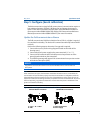
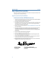
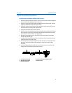
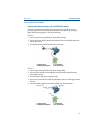
Typical connection head installation
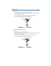
Head mount transmitter with DIN plate style sensor
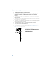
1. Attach the thermowell to the pipe or process container wall. Install and tighten
the thermowell before applying process pressure.
2. Verify the transmitter failure mode switch.
3. Assemble the transmitter to the sensor. Push the transmitter mounting screws
through the sensor mounting plate and insert the snap rings (optional) into
the transmitter mounting screw groove.
4. Wire the sensor to the transmitter (see “Wire and apply power” on page 12 for
more information).
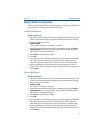
5. Insert the transmitter-sensor assembly into the connection head. Thread the
transmitter mounting screw into the connection head mounting holes.
Assemble the extension to the connection head. Insert the assembly into the
thermowell.
6. Slip the shielded cable though the cable gland.
7. Attach a cable gland into the shielded cable.
8. Insert the shielded cable leads into the connection head through the cable
entry. Connect and tighten the cable gland.
9. Connect the shielded power cable leads to the transmitter power terminals.
Avoid contact with sensor leads and sensor connections.
10. Install and tighten the connection head cover. Enclosure covers must be fully
engaged to meet explosion-proof requirements.
A. 644H Transmitter D. Transmitter mounting screws
B. Connection head E. Integral mount sensor with flying leads
C. Thermowell F. Extension
A
D
B
C
EF