


Quick Start Guide
5
May 2014
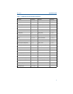
Table 1. Traditional Interface Fast Key Sequences
Function Fast Keys Function Fast Keys
Active Calibrator 1, 2, 2, 1, 3 Open Sensor Holdoff 1, 3, 5, 3
Alarm/Saturation 1, 3, 3, 2 Percent Range 1, 1, 5
AO Alarm Type 1, 3, 3, 2, 1 Poll Address 1, 3, 3, 3, 1
Burst Mode 1, 3, 3, 3, 3 Process Temperature 1, 1
Burst Option 1, 3, 3, 3, 4 Process Variables 1, 1
Calibration 1, 2, 2 PV Damping 1, 3, 3, 1, 3
Callendar-Van Dusen 1, 3, 2, 1 PV Unit 1, 3, 3, 1, 4
Configuration 1, 3 Range Values 1, 3, 3, 1
D/A Trim 1, 2, 2, 2 Review 1, 4
Damping Values 1, 1, 10 Scaled D/A Trim 1, 2, 2, 3
Date 1, 3, 4, 2 Sensor Connection 1, 3, 2, 1, 1
Descriptor 1, 3, 4, 3 Sensor 1 Setup 1, 3, 2, 1, 2
Device Info 1, 3, 4 Sensor Serial Number 1, 3, 2, 1, 4
Device Output Configuration 1, 3, 3 Sensor 1 Trim 1, 2, 2, 1
Diagnostics and Service 1, 2 Sensor 1 Trim-Factory 1, 2, 2, 1, 2
Filter 50/60 Hz 1, 3, 5, 1 Sensor Type 1, 3, 2, 1, 1
Hardware Rev 1, 4, 1 Software Revision 1, 4, 1
Hart Output 1, 3, 3, 3 Status 1, 2, 1, 4
Intermittent Detect 1, 3, 5, 4 Ta g 1, 3, 4, 1
LCD Display Options 1, 3, 3, 4 Terminal Temperature 1, 3, 2, 2,
Loop Test 1, 2, 1, 1 Test Device 1, 2, 1
LRV (Lower Range Value) 1, 1, 6 URV (Upper Range Value) 1, 1, 7
LSL (Lower Sensor Limit) 1, 1, 8 USL (Upper Sensor Limit) 1, 1, 9
Measurement Filtering 1, 3, 5 Variable Mapping 1, 3, 1
Message 1, 3, 4, 4 Variable Re-Map 1, 3, 1, 5
Meter Configuring 1, 3, 3, 4, 1 Write Protect 1, 2, 3
Meter Decimal Point 1, 3, 3, 4, 2 2-Wire Offset 1, 3, 2, 1, 2, 1
Num Req Preams 1, 3, 3, 3, 2