


Quick Start Guide
13
May 2014
Ground the transmitter
Ungrounded thermocouple, mV, and RTD/Ohm inputs
Each process installation has different requirements for grounding. Use the
grounding options recommended by the facility for the specific sensor type, or
begin with grounding option 1 (the most common).
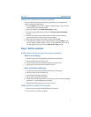
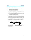
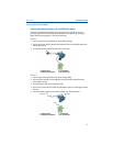
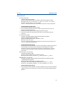
Option 1
1. Connect sensor wiring shield to the transmitter housing.
2. Ensure the sensor shield is electrically isolated from surrounding fixtures that
may be grounded.
3. Ground signal wiring shield at the power supply end.
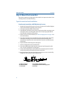
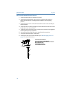
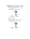
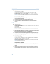
Option 2
1. Connect signal wiring shield to the sensor wiring shield.
2. Ensure the two shields are tied together and electrically isolated from the
transmitter housing.
3. Ground shield at the power supply end only.
4. Ensure the sensor shield is electrically isolated from the surrounding grounded
fixtures.
5. Connect shields together, electrically isolated from the transmitter
A. Sensor wires C. Transmitter
B. Shield ground point D. 4–20 mA loop
A. Sensor wires C. Transmitter
B. Shield ground point D. 4–20 mA loop
C
B
D
A
B
D
C
A