


RUSKA 2470
Users Manual
2-2
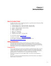
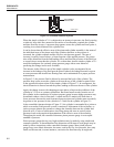
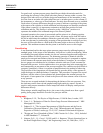
SECONDARY
PRESSURE
PRESSURE IN
glg45.eps
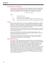
Figure 2-3. Controlled Clearance Cylinder
When the simple cylinder of 2-1 is subjected to an increase in pressure, the fluid, exerting
a relatively large total force normal to the surface of confinement, expands the cylinder
and thus increases its area. A pressure-drop appears across the cylinder wall near point A,
resulting in an elastic dilation of the cylinder bore.
It can be shown that the effective area of the piston and cylinder assembly is the mean of
the individual areas of the piston and of the cylinder; therefore as the pressure is
increased, the cylinder expands and the effective area becomes greater. The rate of
increase is usually, but not always, a linear function of the applied pressure. The piston
also suffers distortion from the end-loading effects and from the pressure of the fluid, but
to a much lesser extent than the cylinder. It is evident then, that the simple cylinder of 2-1
would be inadequate for a primary piston pressure gauge unless some means of
predicting the change in area were available.
The increase in the effective area of the simple cylinder is also accompanied by an
increase in the leakage of the fluid past the piston. Indeed, the leakage becomes so great
at some pressures that insufficient floating time can be maintained for a proper pressure
measurement.
In Figure 2-2, the pressure fluid is allowed to surround the body of the cylinder. The
pressure drop occurs across the cylinder wall near the top of the cylinder at point B, but
in the opposite direction to that of the simple cylinder in Figure 2-1. In consequence, the
elastic distortion is directed toward the piston, tending to decrease the area of the cylinder.
Again, the change in area with changing pressure places a limit on the usefulness of the
cylinder in 2-2 for it as a primary instrument. But some benefit results from the use of
this cylinder in the construction of a piston pressure gauge because higher pressures may
be attained without a loss in float time. A small sacrifice is made in the float time at
lower pressures because the total clearance between piston and cylinder must necessarily
be greater at low pressure for the cylinder in 2-2 than for the cylinder in Figure 2-1.
In the controlled-clearance design of Figure 2-3, the cylinder is surrounded by a jacket to
which a secondary fluid pressure system is connected. Adjustment of the secondary, or
jacket, pressure permits the operator to change the clearance between the cylinder and
piston at will. A series of observations involving piston sink rates at various jacket
pressures leads to the empirical determination of the effective area of the assembly.
Throughout the world, the controlled-clearance piston pressure gauge is an accepted
standard of pressure.
Piston pressure gauges having very high resolutions may be made by using simple and
reentrant cylinders. A determination of the distortion coefficients of such gauges may be
made by direct comparison with a controlled-clearance gauge. Most piston pressure
gauges have some elastic distortion, but some, used in the very low pressures, have only
small coefficients and, in some instances, correction for distortion may be neglected.