


RUSKA 2470
Users Manual
4-2
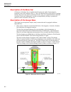
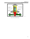
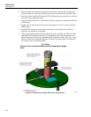
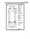
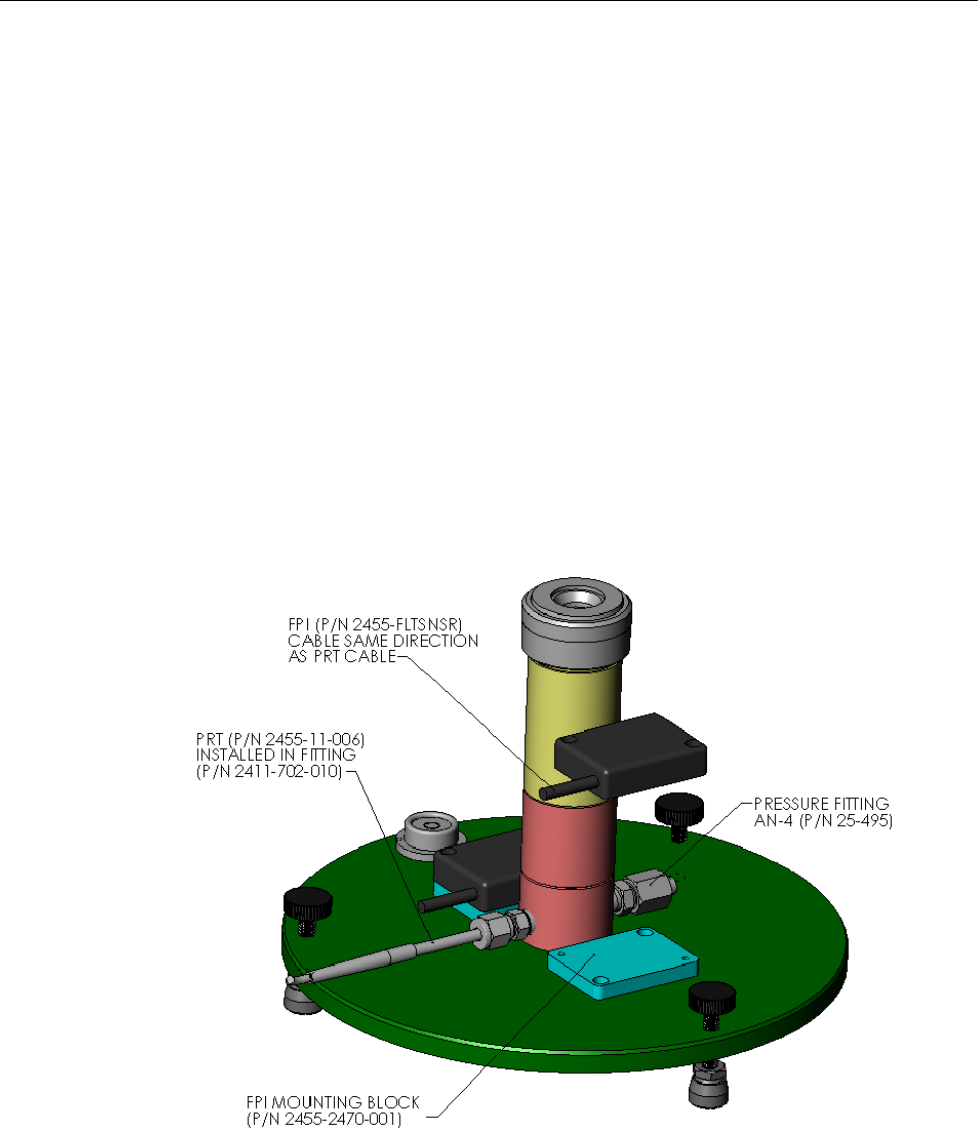
4. Mount the FPIs (Float Position Sensors) to the blocks, orient the FPI sensors such
that their cables are trail away from the base in the same direction as the PRT cable.
5. Route the cables from the FPIs and the PRT such that they do not interfere with other
activities on the calibration bench.
6. Connect the PRT and FPIs to the RUSKA 2456 per instructions found in the RUSKA
2456 Manual.
7. Readjust the leveling screws if necessary until gauge is level in 2 axes by using the
bubble gauge.
8. Install the desired piston and cylinder assembly into the housing. See Chapter 5,
Operation, for operation of the gauge.
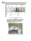
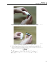
9. If the optional glass thermometer is being used, insert it into the 1/4 NPT hole in the
right hand side of the Base Assembly. The graduated end of the thermometer will
protrude through the hole in the right hand side of the base casting. Here too, a small
amount of heat sink compound applied to the bulb of the thermometer will shorten
the response time of the thermometer.
W Caution
Always remove the thermometer before shipping the gauge
base.
gmq06.bmp
Figure 4-1. FPI Mounting - RUSKA 2456 Piston Gauge Monitor