


Operation
Mid Range Piston Assembly 5
5-7
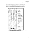
8. Install the weight adapter (P/N 2465-2470-736) to the top of the low range piston
cylinder. Take care to account for the adapter in the pressure calculations.
• Add the Mass of the adapter to the tare for the Piston
• Add the height of the adapter to the L1 dimension for the Cylinder
(approximately .21 inches)
The gauge is now ready for operation.
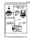
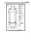
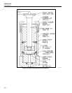
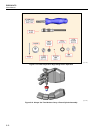
Mid Range Piston Assembly
Refer to Figures 5-8, 5-9, 5-10, and 5-11.
If the Mid Range Piston Assembly is to be used:
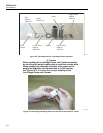
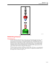
1. The Lower Thrust Bearing (2460-4-25) mentioned in the preceding section,
Chapter 5, Low Range Piston Assembly, must be left in the gauge with the Filter,
Filter Retainer, and O-Ring as described in that section.
2. Next, insert the Lower Cylinder Spacer, O-Ring, and the piston and cylinder after
they have been cleaned according to the instructions in Chapter 6, Piston /Cylinder
Cleaning Instructions. The O-Rings should be lubricated with Dupont Krytox 240
Grease (45-351) before installation. All excess lubricant should be wiped off, leaving
only a slight film.
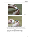
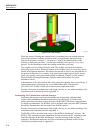
3. Place the Cylinder Retainer (2460-70-2) over the cylinder.
4. Place the Cylinder Retaining Cap (2460-4-7) onto the housing.
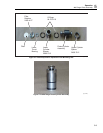
5. Tighten this cap securely by hand while holding the column with the opposite hand.
6. Before proceeding, check the level vial to verify that the base is level, adjust the level
of the base if necessary.
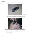
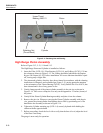
7. Install the weight adapter (P/N 2465-2470-736) to the top of the low range piston
cylinder. Take care to account for the adapter in the pressure calculations.
• Add the Mass of the adapter to the tare for the Piston
• Add the height of the adapter to the L1 dimension for the Cylinder
(approximately .21 inches)
The gauge is now ready for operation.