


3. INSTALLATION
24
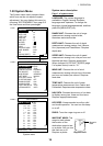
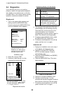
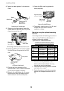
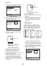
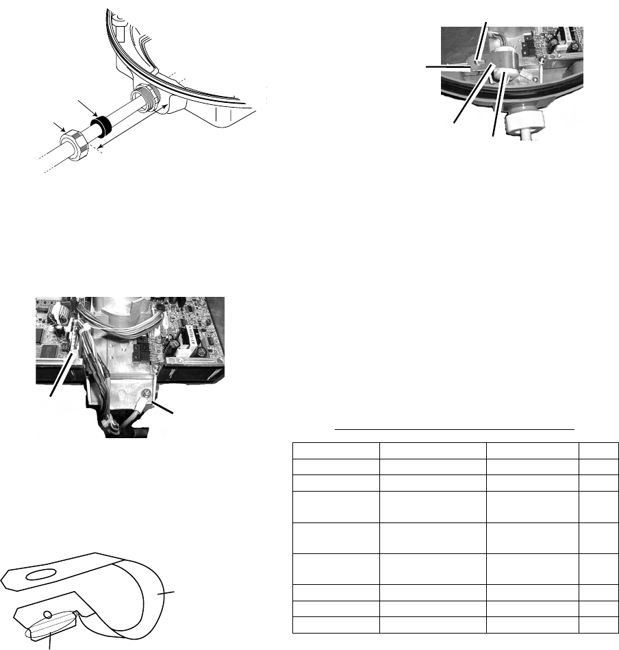
8. Tighten the cable gland to fix the antenna
cable.
Gasket
Cable Gland
Tighten gland so
this length is
within 12 mm.
Antenna unit, inside view
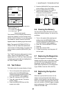
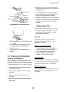
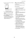
9. Referring to the figure below, fasten the
shield cable with a screw (M4 x 10) on the
chassis to ground the unit.
Connect 9 pin
connector
here (J801).
Connect
shield here.
Connecting antenna cable to antenna unit
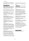
10. Attach the EMI core to the antenna cable.
Set the EMI core fixing band to the EMI
core.
This bend should be
facing to the cable
entrance.
Fixing band
EMI core fixing band
11. Connect the 9-pin connector of the
antenna cable to J801. See the illustration
on the previous page for location.
12. Refasten the shield plate with 10 screws.
Be sure not to pinch the cable from the
rotation detector with the shield plate.
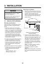
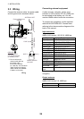
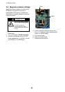
13. Fasten the EMI core fixing plate with
screw (supplied).
Screw (M4 x 15)
EMI Core
EMI Core
Fixing Plate
Align bend with
corner of chassis.
How to fix the EMI core
14. Temporarily close the cover. You will need
to open the cover later to confirm
magnetron voltage.
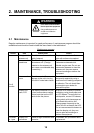
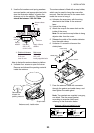
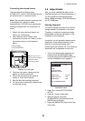
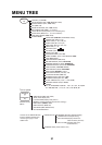
Mounting using the optional mounting
bracket
A mounting bracket for fastening the antenna
unit to a mast (70-125 mm diameter) on a
sailboat is optionally available.
Type OP03-93, Code 008-445-080
Contents of radome mounting assy.
Name Type Code No. Qty
Bolt M4 x 12 000-804-725 4
Bolt M8 x 20 000-805-707 8
Mounting
plate
03-018-9001-0 100-206-740 1
Support
plate (1)
03-018-9005-0 100-206-780 1
Support
plate (2)
03-018-9006-0 100-206-790 1
Bracket (1) 03-028-9101-0 100-206-810 1
Bracket (2) 03-028-9102-0 100-206-820 1
Fixing plate 03-028-9103-0 100-206-830 2
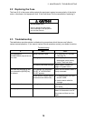
1. Remove mounting hardware at the
bottom of the antenna base. You may
discard the mounting hardware.
2. Assemble the mounting bracket as below
and fasten it to a mast.
3. Fasten the antenna unit to the mounting
bracket with hexagon head bolts (M10 x
25).