


3. INSTALLATION
26
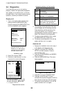
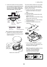
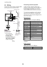
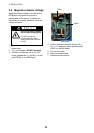
3.3 Wiring
Connect the antenna cable, the power cable
and the ground wire as shown below.
FUSE (5 A)
POWER SUPPLY
12/24 VDC
POWER CABLE
DISPLAY UNIT
ANTENNA UNIT
ANTENNA CABLE
*
WHT (+)
BLK (-)
External Equipment
(NMEA)
GROUND
Connect ground
wire to bolt fastened
(or welded) to hull.
* = Do not confuse the
antenna cable with the
transducer cable
for the Echo Sounder
(ex. LS-6100). The transducer
cable is black; the antenna
cable is white and "RADAR"
is written on the cable.
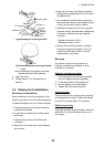
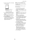
Wiring
Connecting external equipment
A video sounder, navigator, plotter, wind
indicator or GPS receiver GP-310 (320B) can
be connected to the display unit. You will
need an NMEA cable to make the connection.
To connect two navigators, use the optional
cable MJ-A15A7F0004-005. Connect them
referring to the interconnection diagram at the
back of this manual.
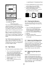
Input sentences
NMEA 0183 Version 1.5/2.0/3.0, 4800 bps
Name Sentences
Ship’s Speed VTG>RMC>RMA>VBW>VHW
Depth DPT>DBK>DBS>DBT
Heading (T)* HDT>HDG>VHW>HDM
Heading (M) HDM>HDG>VHW>HDT
Course (T) VTG>RMC>RMA
Course (M) VTG>RMC>RMA
Range/Bearing RMB>BWR>BWC
Waypoint RMB>BWR>BWC
Own Ship Pos. GGA>RMC>RMA>GLL
Time Diff. RMA>GLC>GTD
Water Temp. MTW
Time, Date ZDA>RMC
Wind Data MWV
Cross-track
Error
RMB>XTE
*Requires magnetic variation (output by
navigator).
Output sentence
NMEA 0183 Version 3.0, 4800 bps
Name Sentence
Target L/L TLL