


SP-2 E3514S01B
4.4 Markers Heading Line, Bearing Scale, Range Rings,
Variable Range Marker (VRM), Electronic Bearing Line (EBL),
Cursor, Alarm Zone, Waypoint Mark*
4.5 Alphanumeric Indications Range, Range Ring Interval, Interference Rejection (IR),
Variable Range Marker (VRM), Electronic Bearing Line (EBL),
Stand-by (ST-BY), Guard Alarm (G (IN), G (OUT), UP RANGE),
Echo Stretch (ES), Range and Bearing to Cursor,
Bearing or L/L Position, Echo Trail (TRAIL), Trail Time,
Watchman (WATCH), Zoomed Display (ZOOM),
Navigation Data*, Heading* *: External data required
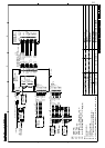
4.6 Input Sentences IEC 61162, NMEA 0183 (Ver1.5/2.0/3.0) GGA, RMC, RMA, RMB,
GLL, VTG, VBW, VHW, HDT, HDG, HDM, BWR, BWC, GLC, GTD,
DPT, DBK, DBS, DBT, MTW, ZDA, MWV, XTE
4.7 Output Sentences IEC 61162, NMEA 0183 (Ver3.0)
TLL (by key operation)
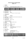
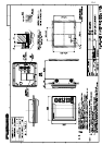
5 ENVIRONMENTAL CONDITIONS
5.1 Ambient Temperature Antenna Unit: -25°C to +55°C, Display Unit: -15°C to +55°C
5.2 Relative Humidity 93% or less at +40°C
5.3 Waterproofing Antenna Unit: IPX6
Display Unit: IPX5 (IPX0 when an external buzzer installed)
5.4 Bearing Vibration IEC 60945
6 POWER SUPPLY
12-24 VDC: 3.5-1.6 A
7 COATING COLOR
7.1 Display Unit N3.0
7.2 Antenna Unit Cover: N9.5, Bottom: 2.5PB 3.5/10
8 COMPASS SAFE DISTANCE
8.1 Display Unit Standard: 0.60 m Steering: 0.40 m
8.2 Antenna Unit Standard: 1.25 m Steering: 0.85 m