


16
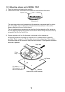
2. WIRING
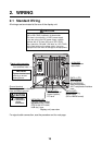
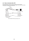
2.1 Standard Wiring
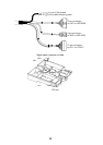
All wirings are terminated at the rear of the display unit.
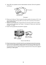
CAUTION
The power cable is shipped with a 10A fuse
(5A on GD-1720C) inserted in its fuse holder.
This fuse is for use with a 12 VDC power supply.
If you are using a 24 VDC power supply, replace
the fuse with a 5A fuse (3A fuse on GD-1720C).
Also, attach the "5A label" ("3A label" on GD-1720C)
to the fuse holder on the power cable. Use of an
improper fuse can result in damage to the equipment.
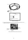
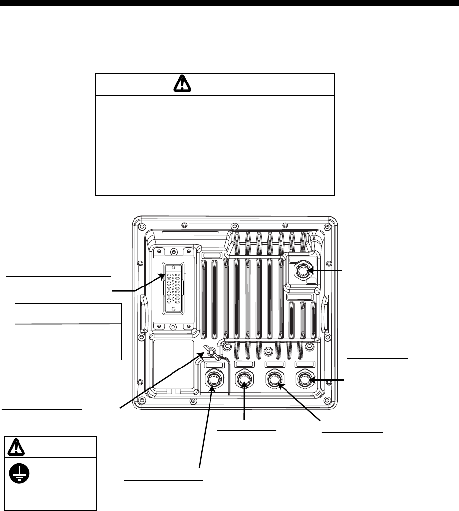
Signal cable connector
Connect signal cable
from antenna here.
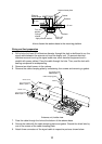
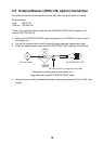
DATA 1 (7P)
Connect
GPS receiver
GP-310B/320B,
NMEA equipment,
AIS Transponder/Interface
here.
DATA 2 (6P)
Connect heading
sensor here.
(AD or NMEA format)
DATA 3 (7P)
Connect external
buzzer (option),
PC here.
NETWORK (6P)
Connect other NavNet
equipment (GD-1720C,
ETR-6/10N, ETR-30N,
HUB etc.) here.
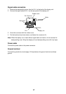
NOTICE
Tighten the boot-band
securely to ensure
watertightness.
12-24 VDC
Connect power
cable here.
Ground terminal
Connect ground wire between
here and ship's ground.
Ground the
equipment to
prevent
interference.
CAUTION
Display unit, rear view
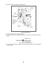
For signal cable connection, see the procedure on the next page.