


iv
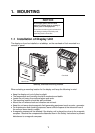
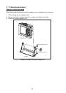
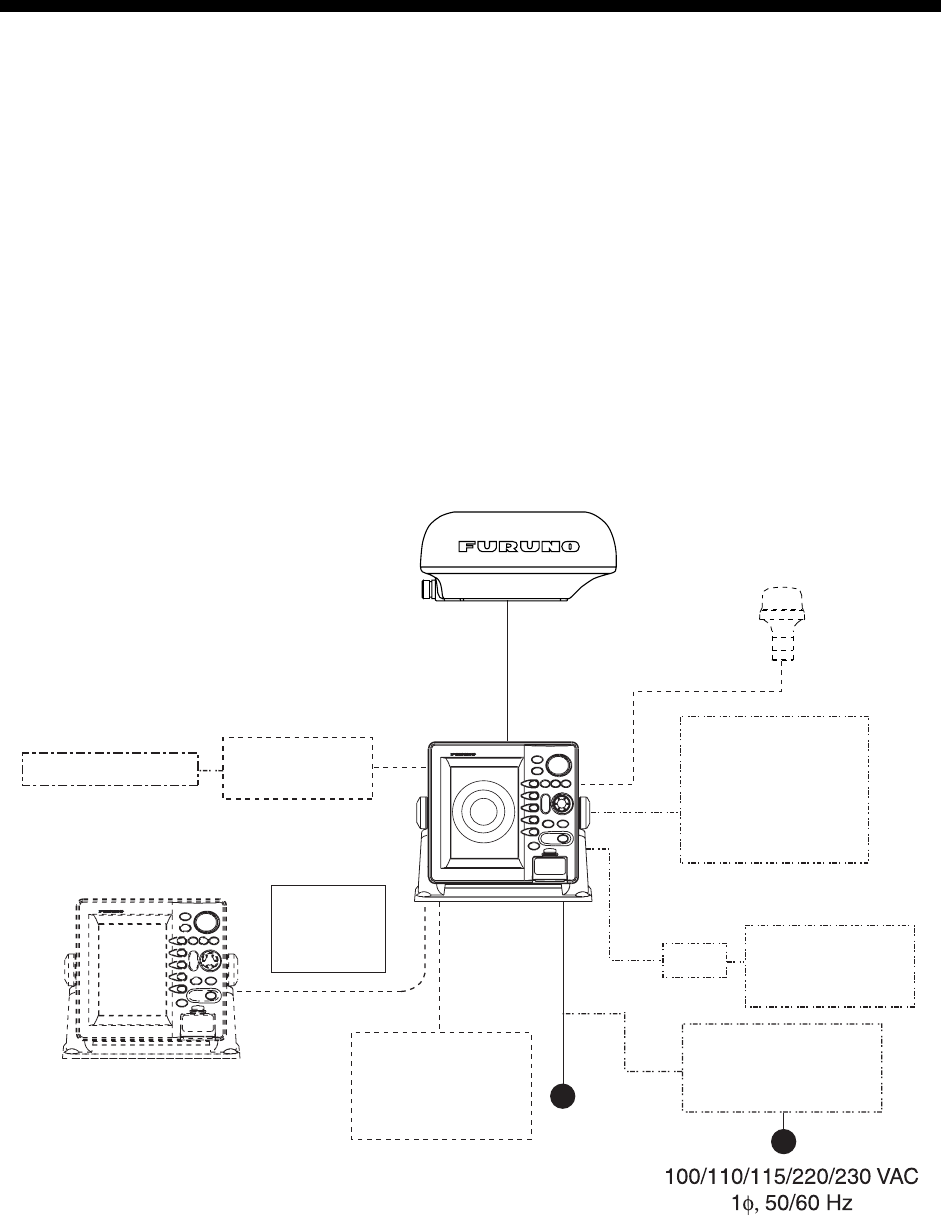
SYSTEM CONFIGURATIONS
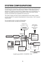
All NavNet products incorporate a “network circuit board” to integrate each NavNet product
on board through an optional LAN cable (Ethernet 10BASE-T). Each NavNet product is
assigned an IP address to enable transfer of images between other NavNet products. For
example, video plotter pictures can be transferred to a radar and vice versa. Pictures
received via the NavNet may be adjusted at the receiving end.
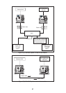
The number of display units which may be installed depends on the number of network
sounder connected. For a system incorporating three or more products, a “hub” is required
to process data.
For one network sounder: one radar and three plotters
For two network sounder: one radar and two plotters
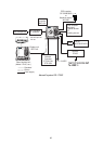
Antenna Unit
(ex. MODEL 1724C)
Network sounder
ETR-6/10N
ETR-30N
12-24 VDC
Other NavNet unit
(GD-1720C, etc.)
Rectifier
PR-62
Display Unit
RDP-148
Remote
Controller
RMC-100
AIS transponder
AIS Interface
IF-1500AIS*
* Not required
for AIS Transponder
FA-150.
HUB
FA-30
AIS RECEIVER
GPS receiver
GP-320B/330B
or
Weather station
WS-200
Echo sounder*
Navigator*
External buzzer
PC
Heading sensor
* NMEA sentence only
NavNet2 system MODEL 1724C/MODEL 1734C