


15
4.4 Fabricating Cable, Assembling Connectors
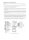
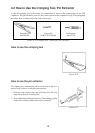
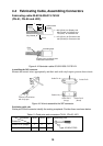
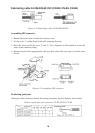
Fabricating cable 00-8016-038-313-761HV
(CN-A1, CN-A5 and J201)
L
45
40
Anticorrosive
sheath
Armor
Vinyl sheath
Shield
Core
Insulating tape
Expose cores, and then wind
shield around the armor.
L = 250 (CN-A1) for Display Unit
320 (CN-A5) for Display Unit
170 (J201) for Interface Unit
L = 470 (CN-A1) for Processor Unit
440 (CN-A5) for Processor Unit
Figure 4-4 Fabrication cable 00-8016-038-313-761HV
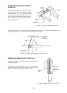
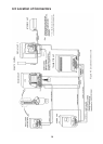
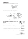
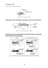
Assembling the 38P connector
Shorten the unused wires appropriately and their ends with vinyl tape to prevent short circuit.
Insulate unused wires
with vinyl tape.
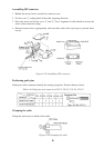
Guide Pin A
Guide Pin B
Position No.
Guide Pin A
(Large)
Guide Pin B
(Small)
Figure 4-5 How to assemble the 38P connector
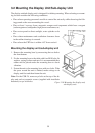
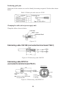
Positioning guide pins
Guide pins of the connector identify the mating receptacle. Position them as shown below.
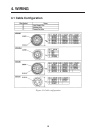
Table 4-1 Guide pins and connectors CN-A1, CN-A5, J201
Connector
Guide Pin
CN-A1 CN-A5 J201
Guide Pin A (Large) 1 5 1
Guide Pin B (Small) 1 1 1
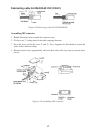
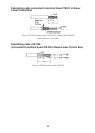
Positioning Tool
Type: 10-910-0179-0