


26
Connections for ES picture and FNZ markers
To provide echo sounder picture and FNZ markers, connect echo sounder to J203 and net
sonde to J202. The signals applied to J202 and J203 are
J202: Net sonde signal and trigger signal (keying pulse of echo sounder). A white line
signal from an echo sounder may be additionally applied as described on the next
page if the digital depth data is not available on J204.
J203: Echo signal and keying pulse from an echo sounder.
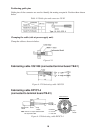
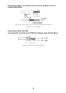
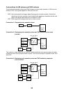
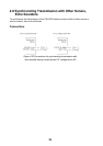
Connection 1: Displaying echo sounder picture
E/S
INTERFACE
UNIT
(CS-120A)
J203
(E/S)
VI-1100A
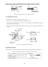
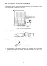
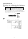
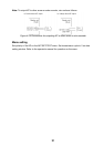
Connection 2: Displaying echo sounder picture and FNZ markers by one echo
sounder
E/S
J203 (E/S)
VI-1100A
J202 (SONDE)
INTERFACE
UNIT
(CS-120A)
SONDE
(FNZ)
SONDE
(FNZ)
SONDE
(FNZ)
1
2
3
FNZ JOINT BOX
(CS-170)
TB-1
TB-2
J701
J705
TB-1
TB-2
This method is used when the net sonde is installed and both echo sounder and net sonde
signals are taken from the same echo sounder. The net sonde signal is applied to both J202
and J203.
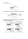
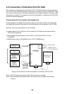
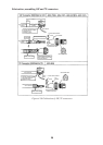
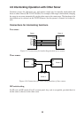
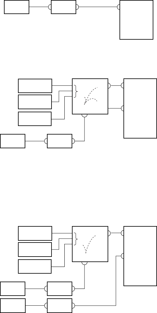
Connection 3: Displaying echo sounder picture and FNZ markers by separate
echo sounders
E/S
J203 (E/S)
VI-1100A
J202 (SONDE)
INTERFACE
UNIT
(CS-120A)
SONDE
(FNZ)
SONDE
(FNZ)
SONDE
(FNZ)
1
2
3
FNZ JOINT BOX
(CS-170)
TB-1
TB-2
J701
J705
E/S VI-1100A