


43
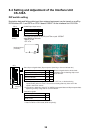
7.3 Connecting cables
Fabricate the cables as shown in the section “4.4 Fabricating Cable, Assembling connectors.”
Connect the cables, referring to the interconnection diagrams at the back of this manual.
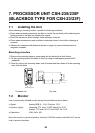
H
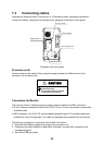
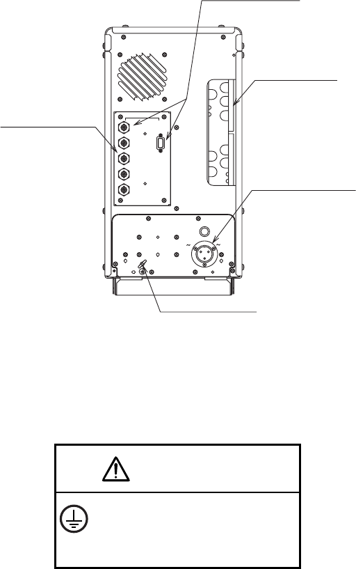
Ground terminal
Power supply port
Cable entrance
Port for monitor
C
3
FUSE
2
1
2A
50/60Hz
100 VAC
GND
5A
D-sub
15P
BNC
R
G
B
H
V
DISPLAY
RGB port panel
Processor unit (rear panel)
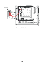
Protective earth
Attach protective earth cable (IV-8sq, shipyard supply) between the GND terminal of the
processor unit and ship’s body.
CAUTION
Securely attach protective earth
to the ship's body.
The protective earth is required
to prevent electrical shock.
Connectors for Monitor
There are two kinds of video signal ports: D-sub connector (default) and BNC connectors.
• D-sub: Use interconnection cable 3COX-2P-6C (5 m or 10 m) or equivalent commercially
available cable.
• BNC connector: Use five 75 Ω coaxial cables (shipyard supply). The coaxial cables are
preferred in case of longer than 10 m cable run between the processor unit and monitor.
The following modification is required to use the BNC connectors.
1. Dismount the RGB port panel at the rear of the processor unit.
2. Confirming the label attached to each BNC connector, connect each connector to its
corresponding port.
3. Mount the RGB port panel.