


40
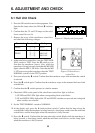
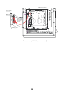
Adjustment of signal level (R36, R56)
1. Set the MODE switch to E/S.
2. Turn the potentiometer R36 to suppress a noise, and the potentiometer R56 so that the
color gradation of the E/S picture on the screen appears similar to the intensity
gradation of the combined E/S echogram.
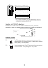
Adjustment of white line inhibit time (R27)
In case digital depth data is not combined with the CS-120A, the white line signal from the
echo sounder is used for depth information. Potentiometer R27 cancels the white line pulse
for about 10 ms after transmission to avoid false depth indication caused by unwanted
noise in short ranges. Readjustment of potentiometer R27 is not required as long as
CSH-23/24 series indicates the correct depth. If does not, however turn R27 to the right.
Adjustment of white line output level (R55)
Improper setting of potentiometer R55 causes the seabed line to be painted in deep blue
due to the white line pulse. Adjust it so that the seabed line is painted in same color as
seabed.
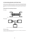
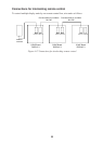
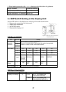
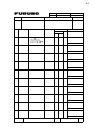
Priority for data
The priority between ports, the category of data or formats is as follows. “1” has the highest
priority.
Basic priority
1. NMEA data > CIF data
2. NMEA data: NMEA port data > CI/NMEA port data
3. CIF data: CI/NMEA port data > CIF port data
Heading priority
1. Heading data from GYRO port
2. GP-HDT from NMEA port (GP-HDT: HDT sentence with Talker GP)
3. GP-HDT from CI/NMEA port
4. VD-VHW from NMEA port
5. VD-VHW from CI/NMEA port
6. VD-CUR from NMEA port
7. VD-CUR from CI/NMEA
8. CIF signal <66> from CI/NMEA port
9. CIF signal <66> from CIF port
GPS fixing position priority
Latitude and Longitude are set to GPS/DR with S3 on the DIP switch DP-1.
1. GP-GGA from NMEA port
2. GP-GGA from CI/NMEA port
3. GP-RMC from NMEA port
4. GP-RMC from CI/NMEA port
5. GP-GLL from NMEA port
6. GP-GLL from CI/NMEA port
7. <28> from CIF port