


1. OPERATIONAL OVERVIEW
1-10
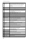
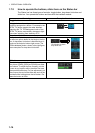
2 Sensor information,
datum box
Shows your ship's heading, heading source, ship's speed, water
tracking speed, speed source, course over ground, speed over
ground, course and speed source, ship's position, position source,
chart datum.
Note: Position source shall meet the requirements of IMO
MSC.112(73).
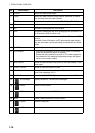
3 Menu Drop-down menu with various radar and chart functions.
4 Information box Provides various navigation data and route information.
5 TT/AIS setting box Sets the parameters for TT and AIS targets.
6 Trail box Sets the parameters for the target trails.
7 Alert box Shows alert messages by alert name and alert number.
• Unacknowledged or regenerated alerts flash in red (alarm) or yel-
low-orange (warning).
• Acknowledged alerts are shown in normal video.
8 Acquisition zone box Sets an acquisition zone for TT, AIS.
9 VRM boxes Shows the range and TTG to the VRM1, VRM2.
10 Target list button Displays the TT and AIS target list.
11 Trial maneuver box Sets the parameters for the trial maneuver.
12 Drop mark 2 box Shows the bearing and range to the drop mark 2.
13 EBL boxes Shows the bearing to the EBL1, EBL2.
14 Mark box Selects the mark to inscribe on the radar display.
15 Drop mark1 box Shows the bearing and range to the drop mark 1.
16 PI line box • Adjusts the direction and width of the parallel index lines.
• Activates or deactivates the parallel index lines.
17 Watch box Counts down the time remaining until the buzzer sounds to alert the
operator to view the radar picture.
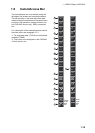
18 InstantAccess bar Quick access to often-used radar, chart radar and chart functions. For
radar and chart radar functions, see section 1.8. For chart functions,
see paragraph 6.1.3.
19 Tuning bar Shows tuning status. (No function with solid state radar.)
20 Range/Presentation
mode box
• Selects the radar range.
• Selects the presentation mode.
21 REF point box Selects the reference point (antenna or CCRP) for measurements
(range, bearing, etc.) and markers (position, etc.)
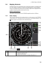
22 Heading line Indicates ship's heading.
23 Bearing scale The bearing scale provides an estimate of the bearing to a target.
24 Cursor position box This box shows
• Latitude and longitude of the cursor position.
• Range and bearing to the cursor position.
• TTG to the cursor position.
25 EBL1
Measures the bearing to a target.
26 EBL2
27 VRM1
Measures the range to a target.
28 VRM2
29 Drop mark 1
Finds the range and bearing to drop mark position.
30 Drop mark 2
31 Antenna marker A cross marks antenna position.
32 Own ship marker An inverted “T” marks your ship’s position.
33 Stern marker Marks location of stern.
34 North marker Marks North.
35 Range rings Provide an estimate of the range to a target.
No. Name Description