


17
A
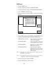
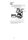
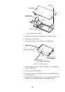
Screws X 4
ANLG Board
GN-7707
Heat sink
Mini pin coax. cable
Mini pin connector
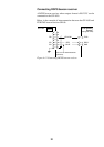
Figure 4-4 Chassis assembly
5. Take off the mini pin coxial cable from J2 on the GN-7707.
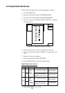
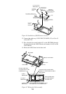
6. Open the lid of GR-7000A.
7. Connect the mini pin coxial cable to J1 of GR-7000A.
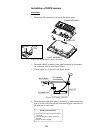
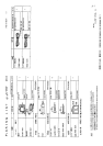
Beacon receiver
GR-7000A
J1
Mini pin coax. cable
J3
Cable assy.
S.FL2-2LP0.7-D-WHT (121)
Notch
Figure 4-5 Beacon receiver
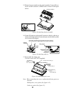
8. Connect cable assy. S.FL2-2LP0.7-D-WHT (121) (supplied) to
J3 of the GR-7000A.
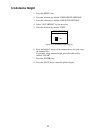
9. Close the lid of the GR-7000A.
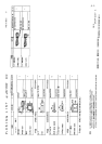
10. Connect connector assy. PH6P-W-L240 to J2 of GR-7000A (Re-
fer to Figure 4-6).
11. Fasten the GR-7000A (Beacon receiver) to the heat sink with four
M3X10 screws (supplied) as shown in the figure below.