


19
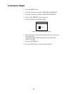
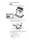
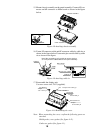
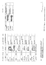
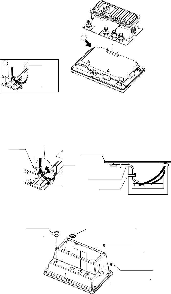
15. Mount chassis assembly on the panel assembly. Connect 8P con-
nector and 6P connector to Main board as shown in the figure
below.
A
View
PH8P
J106
PH6P
J107
(P) MAIN
PANEL ASSEMBLY
CHASSIS ASSEMBLY
Connector
A
Figure 4-8 Attaching chassis assembly
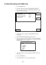
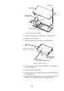
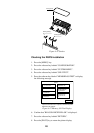
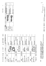
16. Fasten 8P connector cable and 6P connector cable by cable tie as
shown in the figure below. Fasten mini pin coaxial cable by cable
tie as shown in the figure.
ANLG board
Cable tie
J8
Mini pin coax. cable
Note: After connecting, pull up cable to remove slack so
as not to pinch the cable between cover panel assembly.
PH8P
J106
PH6P
J107
MAIN Board
Cable tie
Figure 4-9 Attaching cable tie
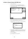
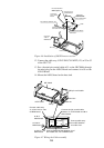
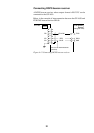
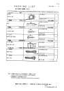
17. Reassemble the display unit.
Use new screws size 3X12 (supplied).
New screws X 6
Screws X 6
Nut
Nut, Washer
COVER ASSEMBLY
Torque:
1.37~1.57 N
m
Torque:
0.74~0.78 N
m
Torque:
0.74~0.78 N
m
Torque: 0.74~0.78 N m
Figure 4-10 Remounting the cover
Note: When reattaching the cover, confirm the following parts are
attached.
.
Shield gasket, cover gasket (See figure 4-11.)
.
Connector gasket (See figure 4-1.)