


4
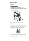
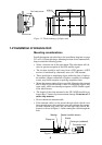
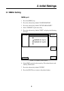
Flush mount
Pan head screws
216±1
164±0.5
4.5
6-R2.25
132±0.5
125±1
Figure 1-3 Flush mounting of display unit
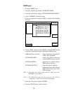
1.2 Installation of Antenna Unit
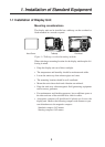
Mounting considerations
Install the antenna unit referring to the installation diagram on page
D-3 or D-4. When selecting a mounting location for the antenna unit,
keep in mind the following points:
• Select a location out of the radar beam. The radar beam will ob-
struct or prevent reception of the GPS satellite signal.
• The location should be well away from a VHF antenna. A GPS
receiver is interfered by a harmonic wave of a VHF antenna.
• There should be no interfering object within the line-of-sight to
the satellites. Objects within line-of-sight to a satellite, for example,
a mast, may block reception or prolong acquisition time.
• Mount the antenna unit as high as possible. Mounting the antenna
unit as high as possible keeps it free of interfering objects and
water spray, which can interrupt reception of GPS satellite signal
if the water freezes.
• The length of the whip antenna for the GP-1650D should be no
longer than 1.2 meter to prevent antenna damage. Do not use a 2.5
meter whip antenna.
• Do not shorten the antenna cable.
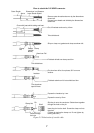
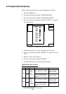
• If the antenna cable is to be passed through a hole which is not
large enough to pass the connector, you may unfasten the connec-
tor with a needle nose pliers and 3/8-inch open-end wrench. Re-
fasten it as shown in Figure 1-4 after running the cable through the
hole.
Center pin (soldered)
Clamp nut
Connector shell
Gasket (reddish brown)Washer
Shield
Figure 1-4 How to assemble the connector