


11GHP 10 Marine Autopilot System Installation Instructions
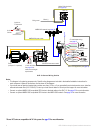
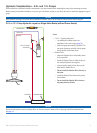
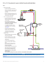
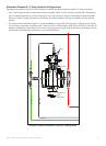
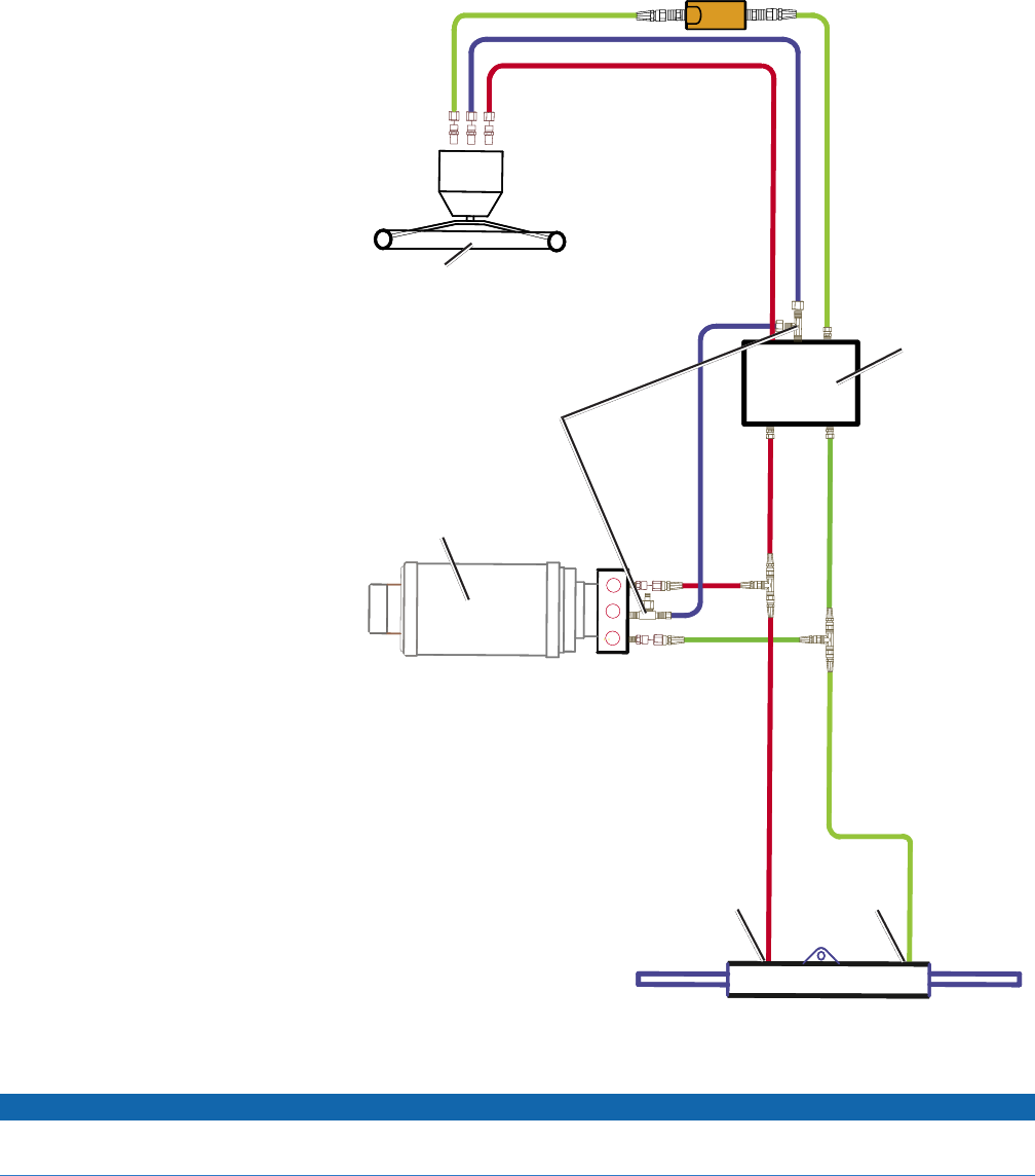
2.0 L or 1.2 L Pump Hydraulic Layout on SeaStar Power Assist-Enabled Boats
Notes:
Power Assist module:
It may be necessary to remove the
Power Assist module to gain access to
the ttings, the hoses, and the bleed-
tee tting.
Remove the bleed-tee tting from the
Power Assist module and relocate it to
the return port on the pump.
2.0 L/1.2 L pump (and motor):
Install the pump to the steering lines
between the cylinder and the Power
Assist module.
Do not install the pump to the
steering lines between the helm and
the Power Assist module.
An unbalanced cylinder requires
an unbalanced valve on the pump
(See page 21)
Mount the pump horizontally if
possible. Do not mount the pump
vertically with the pump end
(hydraulic connections) down.
Shadow Drive:
Mount the Shadow Drive horizontally
and as level as possible.
Install the Shadow Drive in either
the port or the starboard hydraulic
steering line.
Always install a length of hose
between the helm and the Shadow
Drive.
Do not install the Shadow Drive
directly to the helm.
Install the Shadow Drive between the
helm and the Power Assist module.
Do not install the Shadow Drive
between the Power Assist module
and the pump.
Do not install the Shadow Drive between the Power Assist module and the cylinder.
Notice
Do not turn the system on until you bleed all the air from the helm, the Shadow Drive, the pump, and all the hydraulic lines.
See page 34.
•
◦
◦
•
◦
◦
◦
◦
•
◦
◦
◦
◦
◦
◦
◦
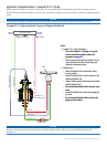
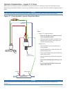
Balanced cylinder
Port tting
Starboard tting
2.0 L/1.2 L pump
(and motor)
Port line
Return line
Starboard line
Shadow Drive
Helm
S R P
Bleed-tee tting
(relocate to the pump)
Sea Star
Power Assist
module
H1 H2
C2C1
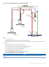
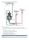
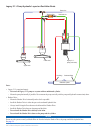
Return line
Balanced cylinder
Port tting
Starboard tting
2.0 L/1.2 L pump
(and motor)
Port line
Return line
Starboard line
Shadow Drive
Helm
S R P
Bleed-tee tting
(relocate to the pump)
Sea Star
Power Assist
module
H1 H2
C2C1
Return line