


29GHP 10 Marine Autopilot System Installation Instructions
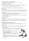
7. Drill the four
1
/
8
in. (3.2 mm) pilot holes.
Notice
If you are mounting the GHC 10 in berglass, it is recommended to use a countersink bit to drill a clearance counterbore through only
the top gel-coat layer. This will help to avoid any cracking in the gel-coat layer when the screws are tightened.
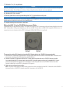
8. Remove the remainder of the template.
9. Place the GHC 10 into the cutout.
10. Securely tighten the four mounting screws through the GHC 10 into the drilled mounting holes.
NOTICE
Stainless-steel screws may bind when screwed into berglass and overtightened. Garmin recommends applying an anti-galling,
stainless anti-seize lubricant to the screws before installing them.
11. Snap the mounting covers into place to install them.
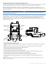
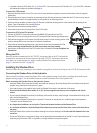
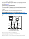
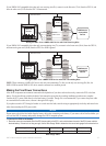
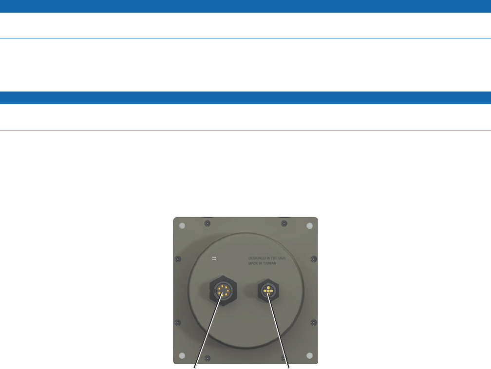
Wiring the GHC 10 to the CCU/ECU Interconnect Cable
Connect the GHC 10 data cable to the yellow CCU signal wire on the CCU/ECU interconnect cable and connect the black wire on the
GHC 10 data cable to CCU ground. Optionally, you can wire the GHC 10 data cable to a NMEA 0183-compatible GPS device to use
waypoint and route information with the GHP 10, although a NMEA 2000 GPS device is preferred.
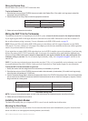
NMEA 0183
data cable
NMEA 2000
drop cable
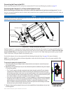
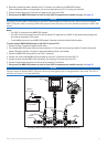
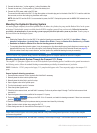
To connect the yellow CCU signal wire from the GHC 10 data cable to the CCU/ECU interconnect cable:
1. Route the GHC 10 data cable to the bare end of the color-coded wires from the CCU/ECU interconnect cable. If the cable is not
long enough, extend the yellow CCU signal wire with 22 AWG wire.
2. Connect the yellow CCU signal wire from the GHC 10 data cable to the yellow wire on the CCU/ECU interconnect cable.
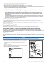
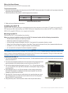
If you install multiple GHC 10 units and want to turn the GHP 10 autopilot system on with any of the installed GHC 10 units,
connect all of the yellow CCU signal wires from the GHC 10 units to the yellow wire on the CCU/ECU interconnect cable.
Connect the black wire on the GHC 10 data cable to CCU ground.
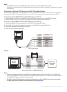
3. Solder and cover all bare-wire connections.
NOTE: The yellow CCU signal wire and the black ground wire must be connected from the GHC 10 data cable to the CCU/ECU
interconnect cable, or the GHP 10 autopilot system will not power on with the GHC 10.