


25GHP 10 Marine Autopilot System Installation Instructions
Installing the Electronic Control Unit (ECU)
To install the ECU, mount it to your boat, connect it to the pump and to the CCU, and wire it to the boat battery.
Installing the ECU on a 24 Vdc System
The ECU hardware has been updated to function with 24 Vdc electrical systems, though older ECU units will only run on 12 Vdc
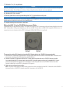
electrical systems. To determine if your ECU is compatible with a 24 Vdc system, examine the serial number on the ECU.
ECU units with a serial number prior to 19E002748 are only compatible with 12 Vdc systems.
ECU units with a serial number of 19E002748 or later are compatible with both 12 Vdc and 24 Vdc systems.
NOTE:
The GHP 10 system software (CCU software) must be version 2.70 or newer in order to support 24 Vdc installations.
Mounting the ECU
Mount the ECU on a preferably at surface within 19 in. (.5 m) of the pump. The cables from the pump cannot be extended. Mount
the ECU in a location where you can run a power wire to the boat battery, but do not connect it to the battery at this time. The power
wire can be extended, if necessary. Use the table on page 33 to determine the correct type of wire for extending the battery cable.
To mount the ECU:
1. Determine the best location for the ECU on your boat, satisfying the wiring considerations.
2. Determine the correct type of screws for the mounting surface. Mounting screws are included with the ECU, but you may need to
provide different screws if the supplied screws are not suitable for the mounting surface.
3. Use the mounting template provided on page 43. Tape the template to the mounting location and use a center punch and hammer
to mark the pilot-hole locations.
4. Drill pilot holes at the four mounting locations.
5. Use screws to mount the ECU.
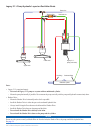
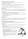
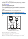
Wiring the ECU
Connect the two wires from the pump to the connectors marked PUMP and ENCODER on the ECU. The connectors are keyed to the
appropriate ttings on the wires. Do not connect the ECU to power until all the connections of the entire GHP 10 system have
been completed (page 33). Wait to connect the CCU/ECU interconnect cable until you have mounted the CCU by following the
procedures in the next section.
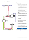
Installing the Course Computer Unit (CCU)
Install the CCU by mounting it to your boat, connecting it to the ECU and to a NMEA 2000 network, and wiring it to the Shadow
Drive, to the tachometer of your boat, to the alarm buzzer, and to the yellow CCU signal wire on the GHC 10.
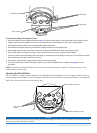
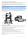
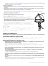
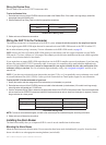
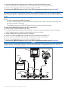
Mounting the CCU
Mount the CCU on the boat by using the included bracket. The CCU bracket has two portions, the mounting portion and the securing
portion. Install the mounting portion on the mounting surface, and secure the CCU in the bracket with the securing portion.
When mounting the CCU:
Mount the CCU in the forward half of the boat, no higher than 10 ft. (3.05 m) above the waterline.
You can mount the CCU below the waterline, as long as it is not in a location where it will be submerged or exposed to wash-
down.
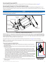
Mount the CCU bracket on a vertical surface or under a horizontal surface, so
that the connected wires hang straight down.
Do not mount the CCU near magnetic material, magnets (speakers and
electric motors), or high-current wires.
Mount the CCU at least 24 in. (0.6 m) away from movable or changing magnetic
disturbances such as anchors, anchor chain, wiper motors, tool boxes, and the
autopilot pump.
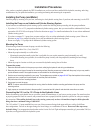
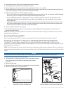
Use a handheld compass to verify the absence of magnetic interference. If the
handheld compass does not point north when you hold it in the location you
want to mount the CCU, then there is magnetic interference. Choose another
location and test again.
•
•
•
•
•
•
•
•
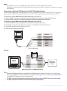
Opening for cables
Mounting
screws (×3)
Thumbscrew
Opening for cables
Mounting
screws (×3)
Thumbscrew