


24 GHP 10 Marine Autopilot System Installation Instructions
4. Disconnect the hydraulic lines from the steering system where appropriate.
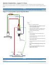
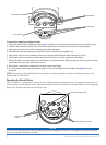
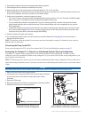
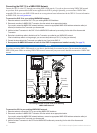
5. Use the diagram above to identify the connectors on the pump.
6. Remove the plugs from the ve connections on the pump labeled C1, C2, H1, H2, and Tank.
7. Route hydraulic hose from the helm to the pump, and from the cylinder to the pump. Be sure to route three hoses to the helm, one
for port, one for starboard, and one for the return line. Add hose if needed.
8. Use the correct connectors to connect the hoses to the pump.
The C1 and C2 ports on the pump are SAE #6 straight-thread O-ring ports, and the H1, H2, and Tank ports are SAE #4 straight-
thread O-ring ports. Do not attempt to thread male pipe-thread ttings into these ports.
The pre-installed ttings adapt from straight-thread O-ring port to female pipe-thread. If needed, male pipe thread to male
straight thread ttings are also included with the pump. Use the included ttings only if they are applicable to your hydraulic
tting conguration.
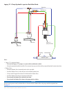
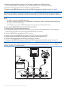
In alternative installations (see page 23) where the helm and cylinder hoses tee together externally and connect to the H ports,
the C ports will remain plugged. If port size is a concern, the plugs can be moved to the H ports and helm and cylinder hoses
can tee into the C ports, as the C ports use the larger SAE #6 tting.
9. Connect the hoses to the helm and to cylinder.
10. You must bleed the hydraulic system, but wait until after you install the Shadow Drive. See page 34 for more information on
bleeding the hydraulic system.
NOTE: The pump may vibrate the hydraulic lines and cause noise when the autopilot is running. To eliminate the noise, secure the
hydraulic lines to a solid surface.
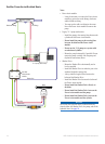
Connecting the Pump to the ECU
Do not connect the pump to the ECU until you have mounted the ECU to the boat following the procedures on page 25.
Conguring the Compact 2.1 L Pump for an Unbalanced-Cylinder Steering Conguration
The compact 2.1 L pump is factory-congured for use with a balanced-cylinder steering conguration. If necessary, it can be
congured to work with an unbalanced-cylinder steering conguration. If you are unsure of the cylinder steering conguration of your
boat, consult the boat manufacturer.
NOTE: The following steps are necessary only if your boat has an unbalanced-cylinder steering conguration. Be sure to follow these
steps before bleeding the hydraulic system. If you remove the check valves after bleeding the hydraulic system, you will need to bleed
it again.
Notice
Keep all parts clean and free of dust and debris while conguring the pump for an unbalanced-cylinder steering system.
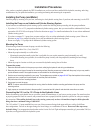
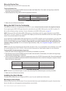
1. Remove the check valves from the pump manifold.
2. Pull the pistons out of the pump manifold. Take note of the piston orientation
as you remove them; you will need to reverse them as part of these
procedures.
3. Remove the Teon rings.
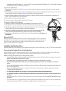
4. Reverse the direction of the Pistons and reinsert them in the pump manifold.
5. Reinstall the check valves on the pump manifold.
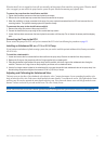
Balanced conguration
Unbalanced conguration
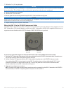
Reversing the Pump Pistons for an
Unbalanced-cylinder Conguration
•
•
•
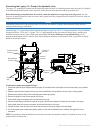
Check valves
Pistons
Teon rings
Removing the Check Valves and Pistons
(Pistons Shown in a Balanced Conguration)
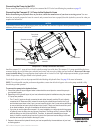
Check valves
Pistons
Teon rings
Removing the Check Valves and Pistons
(Pistons Shown in a Balanced Conguration)