


26 GHP 10 Marine Autopilot System Installation Instructions
If possible, mount the CCU within 16 ft. (5 m) of the ECU. If you cannot mount the CCU within 16 ft. (5 m) of the ECU, extension
and replacement cables are available (see page 4).
To mount the CCU bracket:
1. Determine the best location for the CCU on your boat. Use a handheld compass to ensure that the location is free of magnetic
interference.
2. Determine the correct type of screws for the mounting surface. Mounting screws are included with the CCU, but you may need to
provide different screws if the supplied screws are not suitable for the mounting surface.
3. Use the mounting template provided on page 43. Be sure to install the mounting portion of the bracket with an opening at the
bottom. Tape the template to the mounting location.
4. Drill pilot holes at the three mounting locations.
5. Use screws to secure the mounting portion of the CCU bracket.
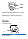
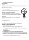
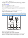
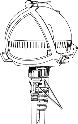
To secure the CCU in the CCU bracket:
1. Connect the CCU/ECU interconnect cable and the NMEA 2000 drop cable to the CCU.
2. Place the CCU in the mounting portion of the CCU bracket with the wires hanging straight down.
3. Place the securing portion of the bracket over the ball and snap it into the mounting portion of the
bracket, starting with the two arms that do not have the thumbscrew.
4. Ensure that the cables hang straight down, and connect the arm with the thumbscrew. The
cables must hang straight down for the CCU to accurately read your heading.
5. Hand-tighten the thumbscrew until the CCU is held rmly in the bracket. Do not overtighten the
thumbscrew.
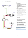
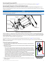
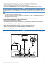
Wiring the CCU
Route the connector-terminated end of the CCU/ECU interconnect cable to the ECU and make the
connection. Do not connect the bare-wire portion of the cable CCU/ECU interconnect cable at this
time. Before you connect the bare-wire portion, install the Shadow Drive and the alarm buzzer
(page 27), and mount the GHC 10 (page 28).
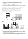
Installing the Shadow Drive
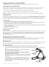
Install the Shadow Drive by connecting it to the hydraulic steering line of your boat and wiring it to the CCU/ECU interconnect cable.
Connecting the Shadow Drive to the Hydraulics
Choose a location at which to connect the Shadow Drive to the hydraulic steering of your boat by consulting the hydraulic-layout
diagrams starting on page 9. Use the included connectors to install the Shadow Drive in the hydraulic line.
When connecting the Shadow Drive to the hydraulic system:
Install the Shadow Drive lower than the helm, but higher than the pump. Mount the Shadow Drive horizontally and as level as
possible, using cable ties to rmly secure it in place.
Avoid making loops in the hydraulic lines. Install the Shadow Drive closer to the helm than to the pump.
Do not mount the Shadow Drive within 12 in. (0.3 m) of any magnetic interference such as speakers and electric
motors.
Do not install the Shadow Drive directly to the ttings at the back of the helm. Install a length of hose between the tting at the
helm and the Shadow Drive.
Do not install the Shadow Drive directly to a hydraulic T-connector in the hydraulic line. Install a length of hose between a
T-connector and the Shadow Drive.
In a single-helm installation, do not install a T-connector between the helm and the Shadow Drive.
In a dual-helm installation, install the Shadow Drive between the pump and the lower helm, closer to the helm than to
the pump.
Install the Shadow Drive in either the starboard steering line or the port steering line. Do not install the Shadow Drive in the
return line.
Do not use Teon tape on any hydraulic tting. Use an appropriate thread sealant such as Loctite Pro Lock Tight multipurpose
anaerobic gel, part number 51604, or equivalent, on all pipe threads in the hydraulic system.
•
•
•
•
•
•
•
•
•
•
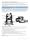
Cables
Thumbscrew
Cables
Thumbscrew