


10 308-017
DISPLACEMENT
PUMP SER
VICE
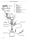
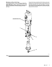
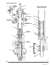
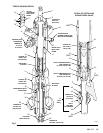
Disassembly
When
disassembling the pump, lay out all removed parts
in
sequence, to ease reassembly
. Refer to Fig 6.
NOTE: Repair
Kit 222-773 is available to replace the pis
-
ton
and intake valve seals. For
the best results,
use all the new parts in the kit. Kit parts are
marked
with one asterisk, for example (1
1*).
Repair Kit 222-774 is available to replace the
throat
packings. For the best results, use all the
new
parts in the kit. Kit parts are marked with two
asterisks,
for example (3**).
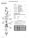
1. Remove the displacement pump from the air motor
as explained on page 9. Place the pump in a vise,
with
the jaws on the outlet housing (10).
2. Hold
the flats of the priming piston rod (24) with a 12
mm wrench. Using a 22 mm wrench, unscrew the
priming
piston nut (30). Slide the priming piston (25)
and
piston guide (31) of
f the rod.
Inspect the surfaces
of
the guide (31) and piston (25) for scoring, wear
, or
other
damage.
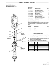
3. Loosen the packing nut (2) using the wrench (1 10)
supplied,
or a hammer and brass rod. Remove the in
-
take
cylinder (23), using an adjustable wrench.
4. Unscrew
the intake valve housing (17) from the
cylin
-
der
(12),
using an adjustable wrench. Pull the hous
-
ing off the pump. The intake check valve assembly
(S)
should slide down the priming piston rod (24)
as
you remove the housing; if it does not slide easily ,
firmly
tap on
the top of the housing (17) with a rubber
mallet
to loosen.
5. Use an o-ring pick to remove the seal (21) from the
intake valve housing (17). Discard the seal; use a
new one for reassembly. Pull the intake valve seat
(22)
out the bottom of
the housing (17). If the seat is
difficult to remove, insert a hammer and brass rod
through the top of the housing and drive the seat
out.Take
care not to drop the check valve assembly
(S) as it comes free, and set it aside for later
.
6. Push
the displacement
rod (1) down as far as possi
-
ble, then pull it and the priming piston rod (24) out of
the
outlet housing (10) and cylinder (12).
7. Remove the packing nut (2), throat packings (3, 5)
and glands (4, 6) from the outlet housing (10). DO
NOT
remove the
fluid outlet nipple (8) and o-ring (9)
from
the housing unless they need replacement.
8. Unscrew
the handle of the bleeder valve (35) from
its
housing.
Clean the threads and the bleed hole in the
valve housing. It is not necessary to remove the
valve
housing from the outlet housing (10).
9. Use
a 400 mm adjustable wrench on the flats of the
pump
cylinder
(12) and unscrew the cylinder from the
outlet
housing (10). Remove the
o-rings (1
1). Inspect
the
inside surface of the cylinder for wear
, scoring or
other
damage by holding it up to the light at an angle
or
running a finger over the surface.
10. Inspect the outer surfaces of the displacement rod
(1) and priming piston rod (24) for wear , scoring or
other damage by holding them up to the light at an
angle
or running a finger over the surface.
11. Use
a vise with soft jaws
to hold the displacement rod
(1)
by its flats.
Place a 19 mm wrench on the flats of
the piston and unscrew the piston (13) and priming
piston rod (24) from the displacement rod (1). Re-
move
the spacer (33). Disassemble the piston guide
(14)
from the piston (13).
12.
It is not necessary to remove the priming piston rod
(24) from the piston (13) unless your inspection re-
veals scoring, wear, or other damage to either part.
To disassemble, place the piston flats in a vise and
unscrew
the rod, using a 12 mm wrench on the flats.
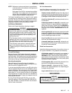
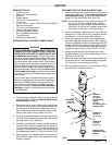
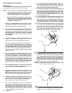
13. Place
the flats of the piston seat (16) in a vise. Using
a
13 mm (1/2 in.) dia. brass rod,
unscrew the piston
guide (14) from the piston seat (16). See Fig 4. Re-
move
the piston seal (15); always replace with a new
one. Inspect the mating surfaces of the piston (13)
and
piston seat (16) for nicks, scoring or wear
.
Fig 4
14
16
BRASS ROD
0205
14. To
disassemble the intake check valve (S), place the
nut
(18) in a vise and unscrew the intake valve body
(19),
using a 28 mm wrench. See Fig 5. Remove the
seals
(42, 20) from the nut and from the valve body;
always
replace them with new ones. Inspect the mat
-
ing surfaces of the intake valve body (19) and seat
(22)
for wear
, scoring, or other damage.
NOTE: The
seal (42) is press-fit in the nut
(18) and may
require
cutting to ease removal.
Fig 5
19
18
0206
15. Inspect all parts for damage and clean with a com-
patible
solvent. T
o reassemble, refer to page 12.