


308-017 5
INSTALLATION
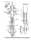
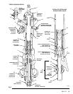
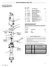
NOTE: Reference numbers and letters in parentheses
in
the text refer to the callouts in the figures and
the
parts drawing.
See pages 22 and 23 for accessories available
from
Graco. If
you supply your own accessories,
be
sure they
are adequately sized and pressure-
rated
to meet the system’
s requirements.
The
T
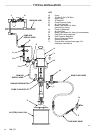
ypical Installation shown on page 4 is
only a guide
for selecting and installing system components and ac-
cessories. Contact your Graco representative or Graco
Technical Assistance (see back page) for assistance in
designing
a system to suit your particular needs.
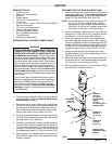
SYSTEM ACCESSORIES
Refer to the T
ypical Installation drawing on page 4.
A
bleed-type master air valve (G) and a fluid drain
valve
(L) are required in your system. These
acces
-
sories help reduce the risk of serious bodily injury
including
splashing in the eyes or on the skin, and
injury from moving parts if you are adjusting or re
-
pairing the pump.
The
bleed-type master air valve relieves air trapped
between this valve and the pump after the air is shut
off.
T
rapped air can cause the pump to cycle unex
-
pectedly.
Locate the valve close to the pump.
The fluid drain valve assists in relieving fluid pres
-
sure in the displacement pump, hose, and gun.
Triggering the gun to relieve pressure may not be
sufficient.
WARNING
Air and Fluid Hoses
Be sure all air and fluid hoses are properly sized and
pressure-rated for your system. Use only grounded air
and
fluid hoses. Fluid hoses must have
spring guards on
both ends. Use of a short whip hose between the main
fluid
hose and the gun allows freer gun movement.
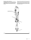
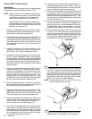
Mounting Accessories
Mount the pump (A) to suit the type of installation
planned. The pump dimensions and mounting hole lay-
outs
are shown on pages 30 and 31.
If you are mounting the pump on a ram (B), refer to the
manual
supplied with the ram unit for
installation and op
-
eration instructions. The ram shown in the T
ypical Instal
-
lation is a 222-781 19 liter (5 gal.) pail ram, used with a
wiper
plate (C).
The ram shown includes an air regulator
.
It
also requires an air supply hose and an air manifold
(D),
which divides the main air supply into separate lines for
the pump and the ram.
By using Pump Mounting Kit 222-776, you can also
mount the pump on Floor Stand 222-780, 200 liter (55
gal.) Ram 223-634, or Inductor 222-635. See Accesso-
ries
for further information.
Air Line Accessories
Install
the following
accessories in the order shown in the
Typical
Installation, using adapters as necessary:
A
pump runaway valve (E
) senses when the pump is
running
too fast and automatically shuts of
f
the air to
the
motor
. A pump which runs too fast can be serious
-
ly
damaged. Install closest to the pump air inlet.
An
air line lubricator (F)
provides automatic air mo
-
tor
lubrication.
A
bleed-type master air valve (G)
is required in your
system to relieve air trapped between it and the air
motor
when the valve is closed (see
the
WARNING
at
left).
Be sure the bleed valve is
easily accessible from
the pump, and is located downstream from the air
regulator.
An
air
regulator (H)
controls pump speed and outlet
pressure by adjusting the air pressure to the pump.
Locate
the regulator close
to the pump, but
upstream
from
the bleed-type master air valve.
An air line filter (J) removes harmful dirt and mois-
ture
from the compressed air supply
.
A second bleed-type air valve (K) isolates the air
line
accessories
for servicing. Locate upstream from
all other air line accessories.
Fluid Line Accessories
Install
the following accessories in the positions shown in
the T
ypical Installation, using adapters as necessary:
A fluid drain valve (L) is required in your system to
relieve fluid pressure in the hose and gun (see the
WARNING at left). Screw the drain valve into the
open
branch of a tee mounted
in the fluid line. Install
the
drain valve pointing down, but so the handle points
up
when the valve is opened.
A fluid regulator (M) controls fluid pressure to the
gun/valve,
and dampens pressure surges.
A gun or valve (N) dispenses the fluid. The gun
shown in the Typical Installation is a dispensing gun
for
highly viscous fluids.
A gun swivel (P)
allows freer gun movement.
GROUNDING
WARNING
Before operating the pump, ground the system as
explained under FIRE OR EXPLOSION HAZARD
and
Grounding
on page 3.