


8 308-017
TROUBLESHOOTING
CHART
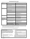
PROBLEM CAUSE SOLUTION
Pump
fails to operate
Restricted line or inadequate air supply
Clear; see
TECHNICAL DATA
on pages 24-29.
Obstructed fluid hose or gun/valve;
fluid hose ID is too small
Open, clear*; use hose with larger ID.
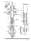
Fluid dried on the displacement rod
Clean; always stop pump at bottom of stroke;
keep wet-cup 1/3 filled with compatible solvent.
Dirty
, worn, or damaged motor parts
Clean or repair; see air motor manual, supplied.
Pump operates, but out-
put
low on both strokes
Restricted line or inadequate air supply
Clear; see
TECHNICAL DATA
on pages 24-29.
Obstructed fluid hose or gun/valve;
fluid hose ID is too small
Open, clear*; use hose with larger ID.
Bleeder valve open
Close.
Air leaking into supply container
Check wiper plate or ram plate seal.
Fluid too heavy for pump priming
Use bleeder valve (see page 6).
Use inductor or ram.
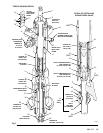
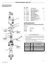
Remove piston spacer (33).**
W
orn packings in displacement pump
Replace packings.
Pump operates, but out-
put
low on downstroke
Fluid too heavy for pump priming
Use bleeder valve (see page 6).
Use inductor or ram.
Remove piston spacer (33).**
Held open or worn intake valve or seals
Clear valve; replace seals.
Pump operates, but out-
put
low on upstroke
Held open or worn piston valve or seals
Clear valve; replace seals.
Erratic or accelerated
pump
speed
Exhausted fluid supply
Refill and prime.
Fluid too heavy for pump priming
Use bleeder valve (see page 6).
Use inductor or ram.
Remove piston spacer (33).**
Held open or worn piston valve or seals
Clear valve; replace seals.
Held open or worn priming piston
Clear; service.
W
orn packings in displacement pump
Replace packings.
*To
determine if the fluid hose or gun is obstructed, follow the
Pressure Relief Procedure W
arning
below
. Disconnect the fluid hose
and place a
container
at the pump fluid outlet to catch any fluid. T
urn on
the air just enough to start the pump (about 1.4-2.8 bar [20-40 psi]).. If the pump starts
when
the air is turned on, the obstruction is in the fluid hose or gun.
**
Remove the piston spacer (33) only as a last resort, as the pump may not perform well without it.
NOTE:
If you experience air motor icing, call Graco T
echnical Assistance
(1-800-543-0339).
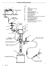
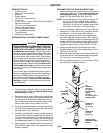
Pressure
Relief Procedure
To
reduce the risk of serious bodily injury
, including fluid injec
-
tion,
splashing in the eyes or on the skin, or injury from mov
-
ing
parts, always follow this
procedure whenever you shut of
f
the
pump, when checking or servicing
any part of the spray/
dispensing system, when installing, cleaning or changing
spray tips/nozzles, and whenever you stop spraying/dis-
pensing.
1. Engage
the spray gun/dispensing valve safety latch.
2.
Shut of
f the air to the pump.
3. Close the bleed-type master air valve (required in your
system).
4. Disengage
the gun/valve safety latch.
5.
Hold a metal part of the gun/valve firmly to the side of a
grounded
metal
pail, and trigger the gun/valve to relieve
pressure.
6. Engage
the gun/valve safety latch.
7. Open
the drain valve (required
in your system) and/or the
pump bleeder valve, having a container ready to catch
the
drainage.
8. Leave
the drain valve open until
you are ready to spray/
dispense
again.
If
you suspect that the spray tip/nozzle or hose is completely
clogged,
or that pressure has not been fully relieved after fol
-
lowing
the steps above,
VER
Y SLOWL
Y loosen the tip guard
retaining nut or hose end coupling and relieve pressure
gradually,
then loosen completely
. Now clear the tip or hose.
WARNING