


12 308-017
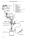
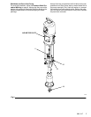
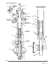
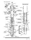
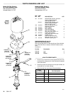
Reassembly (Refer to Fig 7)
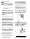
1. Place
a 13 mm (1/2 in.) dia. brass rod lengthwise in
a
vise. Install a new piston seal (15*) on the piston
seat.
Apply thread
sealant to the threads of the piston
seat. Place the piston guide (14) securely on the
brass
rod. Using
a 32 mm crow’
s-foot, screw the pis
-
ton seat (16) into the piston guide. Torque to 27-34
N.m (20-25 ft-lb).
2. If
it was necessary to remove the priming piston
rod
(24)
from the piston (13), apply thread sealant to the
threads
of the rod. Place the flats
of the piston (13) in
a
vise. Hold the flats of the rod with a 12 mm
wrench,
and screw the rod into the piston. T orque to 45-53
N.m (33-39 ft-lb).
3. Use
a vise with soft jaws
to hold the displacement rod
(1)
by its flats. Install the spacer (33, see the
follow
-
ing
note) on the rod. Install the
assembled piston gui
-
de/seat on the piston (13). Apply thread sealant to
the threads of the displacement rod, and screw the
piston
assembly onto the rod, using a 19 mm wrench
on the flats of the piston. T orque to 120-130 N.m
(88-95 ft-lb). There will be a small gap between the
top
of the piston (13) and the shoulder of the rod
(1).
NOTE: The piston spacer (33) is not required when
pumping
fluids with a viscosity greater than 1 mil
-
lion
centipoise.
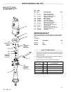
4. Screw the handle of the bleeder valve (35) into the
valve housing. The handle has two sets of threads.
When
reassembling,
be sure to screw the handle ful
-
ly
into the valve housing.
NOTE: It
is not ordinarily necessary to remove the outlet
nipple
(8)
and o-ring (9*). However
, if they were
replaced because of damage, lubricate the o-
ring
(9*) and place it on the nipple (8). Screw the
fitting into the outlet housing (10). T orque to
70-75 N.m (51-55 ft-lb).
5. Lubricate
the o-rings (1
1*) and install them on the
cyl
-
inder (12). Apply thread lubricant to the top threads of
the
cylinder
. Using a 400 mm wrench on the flats of
the cylinder, screw it into the outlet housing (10).
Torque
to 256-297 N.m (190-220 ft-lb).
6. Lubricate
the throat packings and glands, and install
them in the outlet housing (10) one at a time in the
following
order
,
with the lips of the v-packings fac
-
ing down:
male gland (6**), UHMWPE v-packing
(5**),
r
v-packing (3**),
UHMWPE (5**),
(3**),
UHMWPE (5**), and female gland (4**).
Apply
thread lubricant to the packing nut (2) and install the
nut
loosely in the outlet housing.
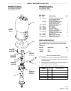
7. Carefully
insert the displacement
rod (1) into the bot
-
tom
of the cylinder (12). Push the rod up into the cyl
-
inder
and through the outlet housing (10), until it pro
-
trudes from the packing nut (2). Be careful not to
damage the piston seal (15*) while performing this
step.
8. Apply thread lubricant to the bottom threads of the
cylinder (12). Be sure the o-ring (11*) is in place on
the
cylinder
. Guide the intake valve housing (17) up
onto
the priming piston rod (24) and screw it onto the
cylinder, using an adjustable wrench. T orque to
256-297
N.m (190-220 ft-lb).
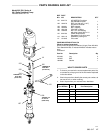
9. With
the beveled side facing up, press the seal (42)
into the recess of the intake packing nut (18) until it
snaps
into place. The
nose of the seal should be flush
with
or slightly recessed into the face of the packing
nut.
10. Apply
sealant to the threads of the intake packing
nut
(18).
With the threads facing down toward the pump
intake, slide the nut up onto the priming piston rod
(24)
until it clears the flats of the rod.
11. Lubricate a new intake valve seal (20*) and slide it
onto the rod, being careful not to damage the seal
when
passing over the flats of the rod. Slide the seal
up
until it reaches the packing nut (18). Apply
sealant
to the female threads of the intake valve body (19),
and
slide it onto the rod until it reaches the nut (18).
12. Place
a 26 mm wrench on the flats of
the packing nut
(18) and a 28 mm wrench on the flats of the valve
body (19). Screw the nut into the body, making cer-
tain
they remain in position above the flats of the rod
(24).
T
orque to 45-53 N.m (33-39 ft-lb). Slide the as
-
sembled
intake check valve up the priming piston
rod
until
it
reaches the stop (T); this may be dif
ficult due
to
high friction between the seal and rod.
13. Position the intake valve seat (22) so its large bev-
eled
side faces down toward the pump intake.
Slide
the
seat (22) onto the priming piston rod (24) and into
the
intake
valve housing (17) until it seats on the low
-
er
lip of the housing. Lubricate a new seal (21*) and
push
it up into the gap around the bottom outer edge
of
the seat (22).
14. Apply
thread lubricant to the
threads of the intake cyl
-
inder (23) and screw the cylinder into the intake valve
housing
(17), using an adjustable wrench. T
orque to
256-297
N.m (190-220 ft-lb).
15. Slide
the priming piston guide (31) onto
the rod (24)
until
it stops. Then install the priming piston (25) with
the flat side of the priming piston (25) facing up to-
ward
the pump. Apply thread sealant to the threads
of the priming piston rod (24). Hold the rod steady
with a 12 mm wrench on the flats, and screw the
priming piston nut (30) onto the rod with a 22 mm
wrench. T
orque to 45-53 N.m (33-39 ft-lb).
16. Reconnect the displacement pump to the air motor
as
explained on page 9.
17. Allow
2 hours for the thread sealant to cure before re
-
turning
the pump to service.
PTFE
PTFE