


Important Two-Component Material Information
3A1570A 11
d. If the swapped module does not fix the problem,
the power module is not the cause.
8. Verify continuity of heater elements with an ohmme-
ter, see page 28.
E02: High zone current
1. Turn main power OFF .
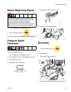
2. Relieve pressure, page 13.
NOTE: Disconnect whip hose.
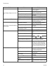
3. Disconnect hose connector (D) at Reactor.
4. Using an ohmmeter, check between the two termi-
nals of the connector (D). There should be no conti-
nuity.
5. Exchange zone module with another one. Turn zone
on and check for error (see page 27). If error disap-
pears, replace faulty module.
For hose zone: If error still occurs, perform Transformer
Primary Check and Transformer Secondary Check,
starting on page 33.
NOTE: When there is a high current error, the LED on
that zone’s module will turn red while the error is dis-
played.
E03: No zone current
1. Check for tripped circuit breaker inside electrical
cabinet or at power source for that zone. Replace
circuit breaker if it trips habitually.
2. Check for loose or broken connection at that zone.
3. Exchange zone module with another one. Turn zone
on and check for error (see page 27). If error disap-
pears, replace faulty module.
4. If E03 occurs for all zones, the 238CR contactor
may not be closing. Verify wiring from heater control
to contactor coil.
a. Hose zone: test hose continuity, page 31.
b. Perform Transformer Primary Check and
Transformer Secondary Check, starting on
page 33.
NOTE: When a no current error occurs, the LED on this
specific zone’s module turns red when the error is dis-
played.
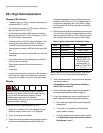
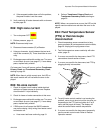
E04: Fluid Temperature Sensor
(FTS) or thermocouple
disconnected
1. Check temperature sensor connections to long
green connector (B) on temperature control module,
page 26. Unplug and re-plug sensor wires.
2. Test fluid temperature sensor continuity with ohm-
meter, page 10.
3. If an error occurred for the hose zone, check FTS
connections at each section of hose.
4. If an error occurred for the hose zone, test FTS by
plugging directly into machine.
5. To verify heater control module is not causing the
problem, use a wire to short-circuit the two pins cor-
responding to the FTS (red and yellow for A or B
zone, red and purple for hose). The display will
show the control heater module temperature.
6. If an error occurred for the hose zone, temporarily
use the current control mode. Refer to Reactor
Operation manual.
F
ti17788a
D