


Repair
30 3A1570A
Thermocouple
1. Turn main power OFF . Disconnect power
supply.
2. Relieve pressure, page 13.
3. Wait for heaters to cool.
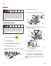
4. Remove heater shroud.
5. Disconnect thermocouple wires from B on tempera-
ture control module. See Table 2, page 26 and F
IG.
6, page 26.
6. Feed thermocouple wires out of cabinet. Note path
as wires must be replaced in the same way.
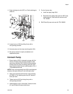
7. See F
IG. 8. Loosen ferrule nut (N). Remove thermo-
couple (361) from heater housing (351), then
remove thermocouple housing (H). Do not remove
the thermocouple adapter (356) unless necessary. If
adapter must be removed, ensure that mixer (360)
is out of the way when replacing the adapter.
8. Replace thermocouple, F
IG. 8.
a. Remove protective tape from thermocouple tip
(T).
b. Apply PTFE tape and thread sealant to male
threads and tighten thermocouple housing (H)
into adapter (356).
c. Push in thermocouple (361) so tip (T) contacts
heater element (358).
d. Holding thermocouple (T) against heater ele-
ment, tighten ferrule nut (N) 1/4 turn past tight.
9. Route wires (S) into cabinet and thread into bundle
as before. Reconnect wires to board.
10. Replace heater shroud.
11. Turn on heaters A and B simultaneously to test.
Temperatures should rise at same rate. If one
heater is low, loosen ferrule nut (N) and tighten ther-
mocouple housing (H) to ensure thermocouple tip
(T) contacts element (358).
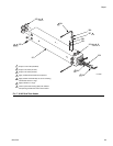
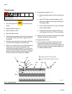
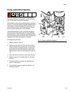
Read Warnings on page 4. Wait for heater to cool
before repairing.
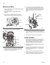
FIG. 8. Thermocouple
360
301
S
N
H
T
358
Apply PTFE tape and thread sealant.
1
1
359
ti7924a
Apply 110009 thermal heatsink compound.
2
2
361
356