


Repair
36 3A1570A
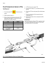
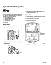
Fluid Inlet Strainer Screen
The inlet strainers filter out particles that can plug the
pump inlet check valves. Inspect the screens daily as
part of the startup routine, and clean as required.
Isocyanate can crystallize from moisture contamination
or from freezing. If the chemicals used are clean and
proper storage, transfer, and operating procedures are
followed, there should be minimal contamination of the
A-side screen.
NOTE: Clean the A-side screen only during daily
startup. This minimizes moisture contamination by
immediately flushing out any isocyanate residue at the
start of dispensing operations.
1. Close the fluid inlet valve at the pump inlet and shut
off the appropriate feed pump. This prevents mate-
rial from being pumped while cleaning the screen.
2. Place a container under the strainer base to catch
drain off when removing the strainer plug (C).
3. Remove the screen (A) from the strainer manifold.
Thoroughly flush the screen with compatible solvent
and shake it dry. Inspect the screen. No more than
25% of the mesh should be restricted. If more than
25% of the mesh is blocked, replace the screen.
Inspect the gasket (B) and replace as required.
4. Ensure the pipe plug (D) is screwed into the strainer
plug (C). Install the strainer plug with the screen (A)
and gasket (B) in place and tighten. Do not over-
tighten. Let the gasket make the seal.
5. Open the fluid inlet valve, ensure that there are no
leaks, and wipe the equipment clean. Proceed with
operation.
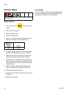
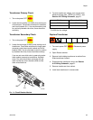
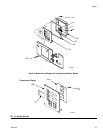
Temperature Display
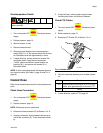
1. Turn main power OFF . Disconnect power
supply.
2. Relieve pressure, page 13.
3. Refer to Reactor A-25 Wiring Schematic, page 51.
4. Put on static conductive wrist strap.
5. Disconnect main display cable (106) at lower left
corner of display module; see F
IG. 15.
6. Remove screws (116) and cover (105); see F
IG. 15.
7. Disconnect cable connector from back of tempera-
ture display (102). See F
IG. 15.
8. Disconnect ribbon cable(s) (R) from back of display;
see F
IG. 15.
9. Remove nuts (103) and plate (101).
10. Disassemble display, see detail in F
IG. 15.
11. Replace board (102a) or membrane switch (102b)
as necessary.
12. Reassemble in reverse order, see F
IG. 15. Apply
medium strength thread sealant where shown. Be
sure display cable ground wire (G) is secured
between cable bushing and cover (105) with screws
(107).
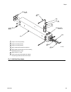
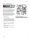
FIG. 14. Fluid Inlet Strainer
A
B
C
D
Ti10974a
NOTICE
Before handling board, put on static conductive
wrist strap to protect against static discharge which
can damage assembly. Follow instructions provided
with wrist strap.