


Repair
3A1570A 31
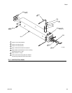
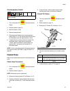
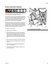
Overtemperature Switch
1. Turn main power OFF . Disconnect power
supply.
2. Relieve pressure, page 13.
3. Wait for heaters to cool.
4. Remove heater shroud.
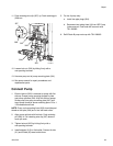
5. Disconnect one leadwire from overtemperature
switch (359), F
IG. 8. Test across switch with ohmme-
ter. Resistance must be approximately 0 ohms.
6. If switch fails test, remove wires and screws. Dis-
card failed switch. Apply thermal compound
110009, install new switch in same location on
housing (351), and secure with screws (311).
Reconnect wires.
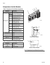
NOTE: If wires need replacement, disconnect tempera-
ture control module. See Table 2, page 26 and F
IG. 6,
page 26
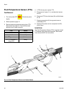
Heated Hose
Refer to the heated hose manual for hose replacement
parts.
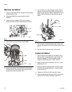
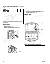
Check Hose Connectors
1. Turn main power OFF . Disconnect power
supply.
2. Relieve pressure, page 13.
NOTE: Whip hose must be connected.
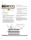
3. Disconnect hose connector (D) at Reactor, F
IG. 9.
4. Using an ohmmeter, check between the two termi-
nals of the connector (D). There should be continu-
ity.
5. If hose fails test, retest at each length of hose,
including whip hose, until failure is isolated.
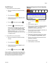
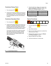
Check FTS Cables
1. Turn main power OFF . Disconnect power
supply.
2. Relieve pressure, page 13.
3. Disconnect FTS cable (F) at Reactor, FIG. 9.
4. Test with ohmmeter between pins of cable connec-
tor.
5. If cable fails test, retest at FTS, page 32.
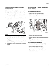
Read Warnings on page 4. Wait for heater to cool
before repairing.
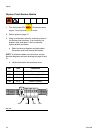
FIG. 9. Heated Hose
Pins Result
1 to 2 approximately 35 ohms per 50 ft (15.2 m) of
hose, plus approximately 10 ohms for FTS
1 to 3 infinity
F
ti17788a
D