


Setup
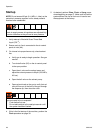
22 3A2012J
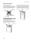
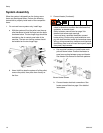
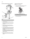
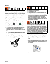
Resin Pump and Optional Heater Connections
6. Verify the pressure relief/recirculation valve (P) is
set to pressure relief.
7. Place a waste container below the fluid outlet then
remove the pump fluid inlet cap. Drain the test oil
then discard.
8. Connect resin suction hose to the resin pump
3/4 nptm fluid inlet (S). Place other end of suction
hose in resin container.
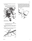
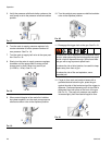
9. For non-heated systems only: Connect resin hose
from the gun hose bundle to the resin pump 1/4 nptf
fluid outlet (R). Reducer fitting comes with Graco
hose bundle.
For heated systems only: attach resin hose from the
gun hose bundle to the heater outlet. Verify fluid
hose connecting resin pump outlet to heater inlet is
installed and secure.
10. Connect resin recirculation hose to the pressure
relief/recirculation line (P1) and route to the resin
container.
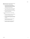
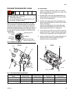
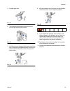
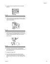
Catalyst Pump Fluid Connections
NOTE: See F
IG
. 3 on page 14.
11. Verify the pressure relief/recirculation valve (W) is
set to pressure relief (knob is horizontal).
12. Connect the catalyst line from the gun hose bundle
to the catalyst outlet (Z1).
F
IG
. 8
S
R
N
M
P
P1
ti18499c
F
IG
. 9: Catalyst Pump Pressure Relief Valve
W
ti21343a