


Repair
48 3A2012J
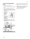
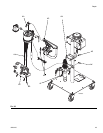
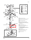
30. Hold spring (911) upright, place valve (912) on top
of spring, slide transfer housing (914) upside down
over the spring then flip upright.
31. Install transfer housing (914) onto piston rod (910).
Use flats on rod and transfer housing to torque
transfer housing against the piston rod to 30-50 in-lb
(3.4-5.6 N•m).
32. Slide the cartridge (902) down against the transfer
housing (914).
33. Install u-cup (915) onto transfer housing with u-cup
opening facing up towards the rod.
34. Install guide (916) onto transfer housing.
35. Install transfer housing cap (917) onto transfer
housing. Use flats to torque to 30-50 in-lb
(3.4-5.6 N•m).
Repair Foot Valve
36. Use wrench to loosen lock nut (921) then remove
cylinder (918) from foot valve (922).
37. Remove ball (925) from foot valve.
38. Remove backup o-ring (920) and o-ring (919) from
both ends of the cylinder (918).
39. Remove ball seat (923). Tool 24N253 can be used
to aid ball seat removal.
40. Place new ball seat onto seat installation tool
16N996 with lip opening facing in towards tool.
41. Place tool into foot valve then tap with a hammer
until ball seat is properly seated then remove tool.
42. Install new backup o-ring (920) and o-ring (919)
onto both ends of the cylinder (918). Make sure to
install the o-rings in the correct position, with the
backup o-rings towards the center of the cylinder.
43. Lubricate the backup o-rings (920) and
o-rings (919).
44. Install ball into foot valve.
45. Thread cross-cut end of cylinder into foot valve by
hand until it bottoms out but do not tighten the jam
nut.
Assemble Catalyst Pump
46. Verify cartridge (902) is pressed against the transfer
housing (914).
47. Lubricate the o-ring (902g) on the cartridge.
48. Apply thread sealant to the threads of the
cartridge (902a).
49. With the slave pump housing (901) in a vise, care-
fully thread the cartridge (902) into the housing.
Torque the cartridge to 240 in-lb (27.1 N•m).
50. Lubricate the o-rings (919, 920) on the
cylinder (918).
51. Hand-thread the cylinder (918) into the slave pump
housing (901) all the way until the cylinder bottoms
out. Rotate the cylinder counterclockwise less than
1/2 turn until the flat on the cylinder is parallel with
the quick-release pin hole then insert the
quick-release pin (908).
52. With the quick-release pin in place, rotate the foot
valve counterclockwise less than one full-turn so
that it is facing directly backwards relative to the
pressure gauge.
53. Hold the foot valve in position and tighten the lock
nut (921) against the foot valve to 225-275 in-lb
(25.4-31.1 N•m).
54. Push the piston rod (908) down into the slave pump
housing (901).