


8
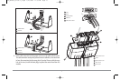
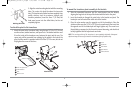
9. While holding cables in place in the cable
collector insert, thread the cables through
the slot in the bottom of the cable collector
cover, line up the cable collector insert and
cover, then slide the cover into place on the
insert.
NOTE: Tab on cable collector insert goes into slot
on cover.
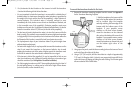
10. Attach the cable collector insert to the
cable collector cover using the 2 Phillip
screws provided.
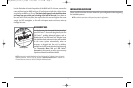
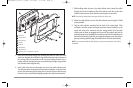
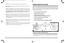
11. Place the unit back onto the mounting bracket. Plug in the cable collector
assembly to the back of the control head. Cable connectors and cable sockets
are keyed to prevent reverse installation, so be careful not to force the
connectors into the wrong sockets. Once the cable collector and all cables
are plugged into the back of the control head, lock the assembly into place
by threading the knurled screw into the threaded insert on the back of the
housing. Adjust the control head to the desired viewing angle and secure by
tightening the gimbal knobs.
NOTE: You may wish to dress the cabling with nylon wire ties in order to hold the cables
together and create a cleaner assembly.
The Humminbird® 900 Series™ control head is now ready for operation.
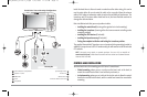
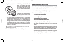
IN-DASH MOUNTING THE CONTROL HEAD
If you are in-dash mounting the control head, start by placing the components on the
surfaces where you intend to install them before installation. Make sure that the
surfaces you have chosen provide adequate protection from wave shock, and that all
cables can reach the control head.
NOTE: If a cable is too short for your application, extension cables are available. Call
Humminbird® Customer Support at 1-800-633-1468 for more information.
Parts and tools specific to In-dash mounting are:
• In-dash mount bracket and threaded rods
• In-dash mounting foam pads
• In-dash mounting template
• Reciprocating saw for cutting dash material
• Masking tape to hold mounting template in place.
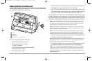
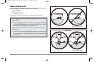
1. Locate a suitable, flat area of the dash to mount the control head. The control
head requires a depth of at least 3 ½ inches (89 mm).
2. Tape the paper In-Dash Mounting template to the desired in-dash mounting
location.
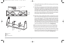
3. At a location inside the dotted line on the template, drill a hole large enough to insert
blade of reciprocating saw. Carefully begin cutting toward the dotted line, then
follow the dotted line around the template. Remove the template when finished.
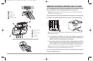
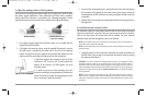
4. Insert and tighten the two threaded rods into the two threaded inserts located
on the back side of the control head. Peel off the adhesive-backed foam pads and
place them on the back of the control head; make sure you notice the difference
between the longer top/bottom and shorter side pads.
Plug Cable Connector Assembly to
Back of Control Head
98x_Manual_531376-1_A.qxd 2/23/2005 11:39 AM Page 14