


22
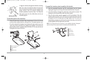
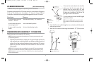
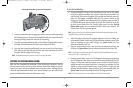
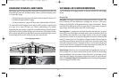
2. Clean the paddlewheel by disengaging the axial clip from the housing wedge
and rotating it forward. Once you have rotated the axial clip, remove it from the
housing by sliding it away from the holes in the housing.
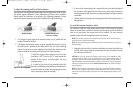
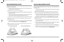
3. Clean the removed paddlewheel with a mild solution of biodegradable soap or
hot water. Clean the wheel well of debris and/or algae at this time.
4. Once you have cleaned the paddlewheel, you may re-insert it into the housing.
Next, slide the axial clip back into the holes, then rotate it backwards to lock it
into place with the wedge in the housing.
NOTE: The paddlewheel must be oriented so that it is scooping the water.
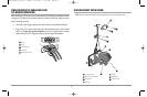
TESTING THE SYSTEM INSTALLATION
After you have completed the installation of the control head, transducer, and any
other accessories such as the GPS receiver, and have made all the cabling connections
required, you must test the installation before using the system. Thorough testing
should be performed with the boat in the water; however, you can confirm basic
operation initially with the boat out of the water as well.
To test the installation:
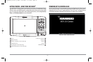
1. Press the POWER/LIGHT key on the control head once to turn on the control
head. (There will be an audible chirp to let you know that you pressed the key,
and the initial Title screen will appear.) If the control head does not power up,
make sure that power is available. While the Title screen is shown on the
display, press the MENU key to display the Start-Up Options menu. Use the UP
or DOWN 4-WAY Cursor keys to position the cursor, then the RIGHT Cursor key
to select System Status from the Start-Up Options menu (see the Start-Up
Options Menu section for more information about these menu choices). The
System Status Self Test screen will appear.
NOTE: If you wait too long, the system will default to whichever menu mode happens to be
highlighted, and you will have to start again.
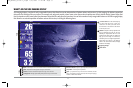
2. Self Test displays results from the internal diagnostic self test, including unit
serial number, Printed Circuit Board (PCB) serial number, software revision, total
hours of operation and the input voltage. See System Status for more
information about the Self Test.
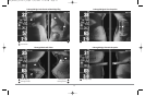
3. From the System Status screen, view accessory connections by pressing the
VIEW key. See System Status for more information about the Accessory Test.
NOTE: The speed accessory (if attached) will be detected only if the paddlewheel has moved
since your 900 Series™ was powered up.
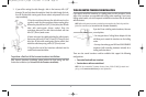
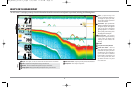
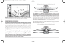
4. From the System Status screen, see a GPS Diagnostic View by pressing the View
key. GPS Diagnostic View shows a sky chart and numerical data from the GPS
receiver. The sky chart shows the location of each visible GPS satellite with its
satellite number and a signal strength bar. A dark grey bar indicates that the
satellite is being used to determine your current position. A light gray bar
indicates that the satellite is being monitored, but is not yet being used. See
System Status for more information about the GPS Diagnostic View.
NOTE: The GPS Diagnostic View is only available on the 987c SI Combo model.
Rotating Retaining Axial Clip to Remove Paddlewheel
98x_Manual_531376-1_A.qxd 2/23/2005 11:39 AM Page 28