


ICOM-200 / 201
Opto inputs
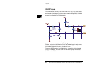
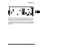
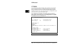
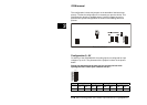
The ICOM-200/201 has eight optocoupler inputs suited for an input voltage
range of 5...12 VDC. To use higher input voltages, as 24V for example, an
additional serial resistor in the input line is used. The resistor value is selected
in accordance to 4...50mA input current needed for the logical “1” level.
2
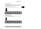
The internal resistance is 680 Ohm / 0,25 W. If now another input voltage is
needed, the totally required resistance can be calculated with the following
formula:
R
ges
= (U
E
-1,3V)/I
D
U
E
= Input voltage
I
D
= Current into the optocoupler
R
ges
= Total resistance
Example:
Is e.g. an input voltage of 24 V with a current of 10 mA wanted, you get
from the above formula R
ges
= 2270 Ohm. This means either the internal
680 Ohm resistor has be replaced with a 2200 Ohm resistor (rounded to
norm value), or a resistor of 1500 Ohm has to be connected in series.
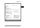
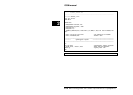
The optocoupled inputs are realized as extended inputs of the Tiny Tiger.
They can be accessed under logical port address 11h (physical 1).
Both USER_EPORT instructions in the sample program are urgent.
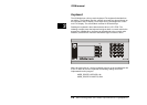
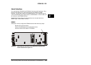
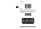
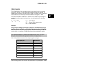
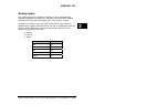
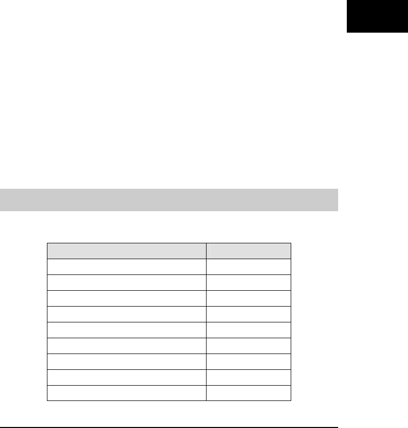
Optocoupler pin DB37 socket
Opto In0 6
Opto In1 25
Opto In2 7
Opto In3 26
Opto In4 8
Opto In5 27
Opto In6 9
Opto In7 28
GND 10
Wilke Technology GmbH • 0241 / 918 900 • http://www.wilke.de/ • support@wilke.de 2-11