


ICOM-manual
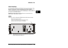
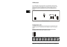
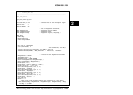
The configuration is done with jumpers on the backside of the board (see
picture). To alter the configuration it is neccessary to open the device. This
should only be done by a qualified person. How the jumpers have to be
placed for the specific configurations is shown in the following table and
pictures.
2
Backside of board
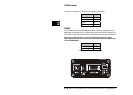
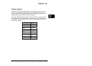
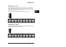
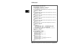
Configuration 0...5V
On delivery of the ICOM-200/201 the analog inputs are configured for input
voltages of up to 5V. The placement of the jumpers is shown in the picture
below.
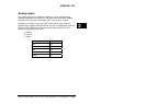
Please pay attention that the keys are free and may fall out while
opening the case. Please open it buttom side up !
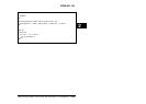
Analog 0 Analog 1 Analog 2 Analog 3
J11 J12 J13 J15 J14 J17 J16 J18
0-5V 1 -3 1 - 2 1 - 3 1 - 2 1 - 3 1 - 2 1 –3 1 - 2
2-16
Wilke Technology GmbH • 0241 / 918 900 • http://www.wilke.de/ • support@wilke.de