


9
1
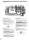
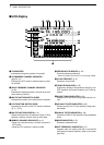
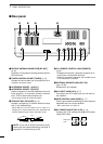
PANEL DESCRIPTION
1ß
VFO
14.195.000
VFO
USB
USBUSB
14.100.00
14.205.00014.205.000
USB
USBUSB
14.100.00
5656
ß
MARKER
MARKER
HOLD
HOLD
MAX-H
MAX-H
EXIT
EXIT
ANT
1
METER
Po
P.AMP
OFF
ATT
OFF
AGC
MID
VOX
OFF
COMP
OFF
SPANSPAN
TX
2.4k2.4k9 2.8k2.8k455455
12:3412:34
Grid
2.5k
10dB
-12.5kSPECTRUMSCOPE+12.5k
320320APFAPF
r
t
i
i
!5 !3!4 !2 !1 !0 o
y
u
u
q
w
e
w
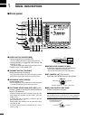
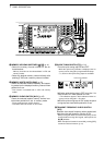
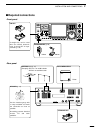
■ LCD display
q TX INDICATOR
Indicates the frequency readout for transmit.
w VFO/MEMORY CHANNEL INDICATOR
(pgs. 22, 41)
Indicates the VFO mode or selected memory chan-
nel number.
e SELECT MEMORY CHANNEL INDICATOR
(p. 50)
Indicates the displayed memory channel is set as a
select memory channel.
r MULTI-FUNCTION SWITCH GUIDE
Indicates the function of the multi-function switches.
t LCD FUNCTION SWITCH GUIDE
Indicates the function of the LCD function switches
([F-1] – [F-5]).
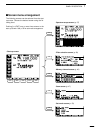
y MULTI-FUNCTION SCREEN (p. 10)
Shows the screens for the spectrum scope, IF filter
selection, memory channel, scan or set modes.
u MEMORY CHANNEL READOUTS (p. 41)
•Show the selected memory channel contents in
VFO mode.
•Show the VFO contents in memory mode.
i FREQUENCY READOUTS (p. 23)
Show the operating frequency.
- Outline characters are used for non-accessing readout.
o CLOCK READOUT (p. 51)
Shows the current time.
!0 TWIN PBT INDICATOR (p. 25)
Graphically displays the passband width for twin
PBT operation and center frequency for IF shift op-
eration.
!1 QUICK TUNING INDICATOR (p. 24)
Appears when the quick tuning step function is in
use.
!2 455 kHz IF FILTER INDICATOR (p. 28)
Shows the 455 kHz IF filter selection using pass-
band width.
!3 9 MHz IF FILTER INDICATOR (p. 28)
Shows the 9 MHz IF filter selection using passband
width.
!4 MODE INDICATOR (p. 25)
Shows the selected mode.
!5 APF FREQUENCY INDICATOR (p. 27)
Appears when the audio peak filter is turned ON
and shows the boost frequency width of the audio
peak filter.