


4 - 2
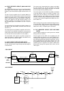
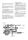
4-1-5 DSP RECEIVER CIRCUIT (MAIN AND DSP
UNITS)
The DSP (Digital Signal Processor) circuit enables digital IF
filter, digital noise reduction, digital PSN (Pulse Shift
Network), phase demodulation, digital automatic notch, and
etc.
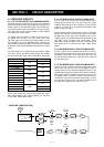
The 3rd IF signal is applied to the IF amplifier (MAIN unit;
IC1002, pin 5) after being passed through the low-pass filter
(MAIN unit; IC1002, pins 3, 1). The amplified 12 kHz 3rd IF
signal is amplified at the differential amplifiers (IC9651a/b),
and is then applied to the A/D convertor section in the
CODEC IC (IC9501) on the DSP board. At the same time,
the converted signal is level-shifted 5 V to 3.3 V in the IC
(IC9501).
The level-shifted signal is applied to the DSP IC (IC9301) for
the digital IF filter, demodulator, automatic notch and noise
reduction, etc.
The output signal from the DSP IC is applied to the D/A con-
verter section in the CODEC IC (IC9501) to convert into the
analog audio signals. Also the signals are level-shifted 3.3 V
to 5 V at the level converter section in the IC (IC9501).
The level-shifted audio signals are passed through the
active filter (IC9701a), and then applied to the MAIN unit via
J9901 (pin 22) as the “DSP02” signal.
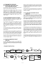
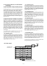
4-1-6 AGC CIRCUIT (DSP AND MAIN UNITS)
The AGC (Automatic Gain Control) circuit reduces IF ampli-
fier gain and attenuates IF signal to keep the audio output at
a constant level.
The receiver gain is determined by the voltage on the AGC1
line from the DSP unit. The D/A converter for the AGC
(IC9102) supplies control voltage to the AGC1 line and sets
the receiver gain with the [RF/SQL] control.
The 3rd IF signal from the CODEC IC (IC9501) is detected
at the AGC detector section in the DSP IC (IC9301). The
output signal from the DSP IC is level-shifted at the level
converter (IC9101) and applied to the D/A converter
(IC9102). The AGC voltage is amplified at the buffer amplifi-
er section in the IC9102 and applied to the MAIN unit to con-
trol the AGC1 line.
When receiving strong signals, the detected voltage increas-
es and the AGC1 voltage decreases. As the AGC1 voltage
is used for the bias voltage of the IF amplifiers (MAIN unit;
Q203, Q401, Q501), IF amplifier gain is decreased.
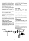
4-1-7 AF AMPLIFIER CIRCUIT (DSP AND MAIN
UNITS)
The AF amplifier amplifies the audio signals to the suitable
driving level for the speaker.
The AF signals from the DSP unit are applied to the AF
amplifier (MAIN unit; IC1651, pin 3) via the “DSPO2” line.
The signals are amplified at the other AF amplifier (IC1651,
pin 5) after being passed through the low-pass filter. The sig-
nals are applied to the AF mute switch (IC1602, pin 2), and
then amplified at the AF power amplifier (IC1601, pin 1). The
amplified signals are applied to the speaker (SP-26) after
being passed through the speaker jack (J1451) via the
“AFO” signal.
DSP
UNIT
IC1101
AGC1
2
6
1
7
AGC2
AGC
AGC
IC1002
DSPI1
IF
amp.
Q501
IF
amp.
Q401
IF
amp.
Q203
From the
antenna
IF
amp.
Differential
converter
IC9651b/a
DSP UNITMAIN UNIT
CODEC IC (IC9501)
IC9301 IC9701a
DSPO1
AF
signals
DSPI1
(12 kHz)
3rd IF
signal
A/D
converter
D/A
converter
Level
converter
Active
filter
Level
converter
DSP IC
• DSP CIRCUIT
• AGC CIRCUIT