


4 - 10
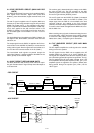
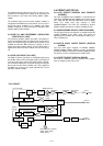
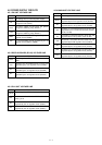
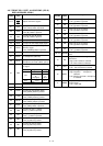
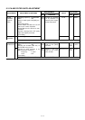
4-6-7 FRONT CPU PORT ALLOCATIONS (RC-26,
DISPLAY BOARD; IC8201)
Pin
number
15–17
21
22
23
24
25
27
28
31
32
37
39
40
48
49
50
51
52
53
54
55
57
Port
name
CS
WR
RD
CALK
UPK
UNK
SELA
SELB
PCON
IOK
MUDK
MPTT
DIM
ETXD
ERXD
SCNK
TUNK
MUTK
EMGK
TRK
TLK
T0K
T9K
T8K
Description
Outputs LCD drive signals.
Input port for the [CALL] switch.
Low: [CALL] switch is pushed.
Input port for the [
∫] switch.
Low: [∫] switch is pushed.
Input port for the [
√] switch.
Low: [√] switch is pushed.
Input port for the select dial A signal.
Input port for the select dial B signal.
Input port for the [POWER] switch
detection signal.
Low: [POWER] switch is pushed.
Input port for the [I/O] switch.
Input port for [
∫], [√] switches from
the microphone (HM-143).
Input port for the [PTT] switch from the
microphone connector (J8701, pin 5).
Outputs LCD back light dimmer con-
trol signal.
Outputs cloning data.
Input port for cloning data.
Input port for the [SCAN] switch
Low: [SCAN] switch is pushed.
Input port for the [TUNE] switch
Low: [TUNE] switch is pushed.
Input port for the [MUTE] switch
Low: [MUTE] switch is pushed.
Input port for the [EMG] switch
Low: [EMG] switch is pushed.
Input port for the [
←] switch
Low: [
←] switch is pushed.
Input port for the [
→] switch
Low: [
→] switch is pushed.
Input port for the [0] switch
Low: [0] switch is pushed.
Input port for the [9] switch.
Low: [9] switch is pushed.
Input port for the [8] switch.
Low: [8] switch is pushed.
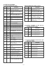
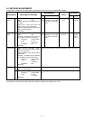
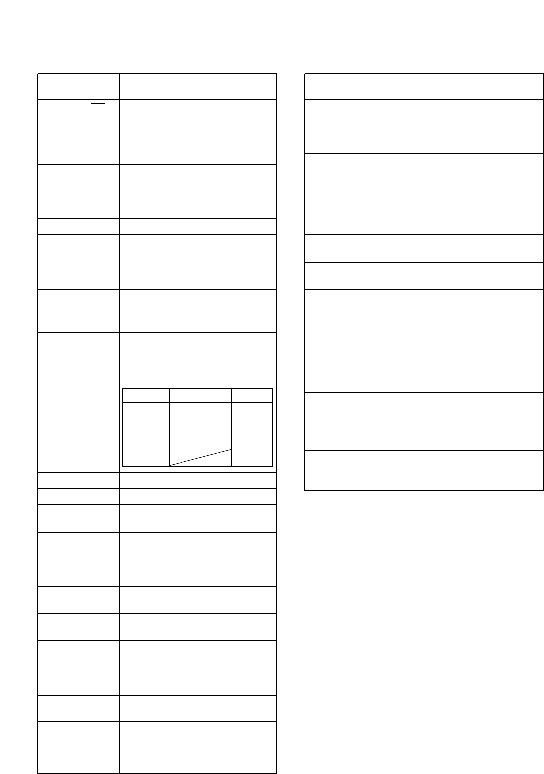
Pin
number
58
59
60
61
62
63
64
65–72
74
75
76
77
Port
name
T7K
T6K
T5K
T4K
T3K
T2K
T1K
DB0–DB7
RS
RES
MSEL
MBKS
Description
Input port for the [7] switch.
Low: [7] switch is pushed.
Input port for the [6] switch.
Low: [6] switch is pushed.
Input port for the [5] switch.
Low: [5] switch is pushed.
Input port for the [4] switch.
Low: [4] switch is pushed.
Input port for the [3] switch.
Low: [3] switch is pushed.
Input port for the [2] switch.
Low: [2] switch is pushed.
Input port for the [1] switch.
Low: [1] switch is pushed.
I/O ports for LCD driver control sig-
nals.
Outputs resistor select signal for the
LCD driver.
High: Index resistor is selected.
Low: Data resistor is selected.
Outputs reset signal for the LCD driver.
Low: The LCD driver is reseted.
Outputs mic gain select signal.
High: Capacitor microphone is
selected.
Low: Moving-conductor microphone
is selected.
Outputs microphone key back light
control signal.
Low: Lights ON.
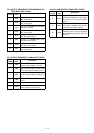
Dimmer Brightness Voltage
0 (dark) 0 V
ON
1 0.8 V
to to
10 (bright) 3.6 V
OFF 5.6 V